


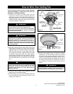

Before assembly your ceiling fan, refer to section on
proper method of wiring your fan (page 9). If you feel
you do not have enough wiring knowledge or
experience, have your fan installed by a licensed
electrician.
WARNING
!
This Manual Is Designed to Make it as Easy as Possible for You to Assemble,
Install, Operate and Maintain Your Ceiling Fan
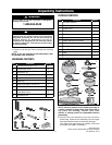
Tools Needed for Assembly
One Phillips head screwdriver One stepladder
One 1/4” blade screwdriver One wire stripper
Materials
Wiring outlet box and box connectors must be of type
required by the local code. The minimum wire would be
a 3-conductor (2-wire with ground) of following size:
Installed Wire Length
Wire Size A.W.G.
Up to 50 ft. 14
50-100 ft. 12
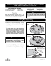
Ceiling Fan Assembly
4
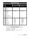
ETL Model No.: CF110
MOTOR HOUSING
SCREWS
MOTOR HOUSING
Figure 1
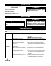
MOTOR HOUSING
SCREWS
LOWER GLASS
RETAINER
ROTATE LOWER
GLASS RETAINER
CLOCKWISE
Figure 2
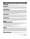
#10-32 x 5/16" SLOTTED
PHILIPS WASHER HEAD
SCREWS (4 per blade assembly)
BLADE
FLANGE
FAN BLADE
#10 PAPER WASHERS (4 per
blade assembly)
Figure 3
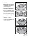
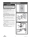
1. Remove one of the motor housing screws and retain
for future use. Loosen the remaining three motor
housing screws for assembly of the lower glass
retainer (Figure 1).
2. Place the lower glass retainer onto the motor housing
and engage the key holes of the retainer onto the
three motor housing screws. Rotate the lower glass
retainer clockwise and tighten the three motor
housing screws. Reinstall the motor housing screw
(previously removed) into the remaining hole of the
lower glass retainer and tighen all screws securely
(Figure 2).
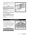
To reduce the risk of personal injury, do not bend the
blade flange when installing the blade flanges,
balancing the blades or cleaning the fan. Do not insert
foreign objects in between rotating fan blades.
WARNING
!
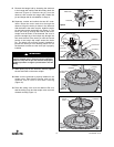
3. Mount blade flange to fan blade using four
#10-32 x 5/16” slotted Phillips washers head screws
and four paper washers (Figure 3). Repeat this
procedure for the remaining four blades and flanges.