


6
ETL Model No.: CF921
Electrical Requirements
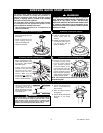
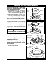
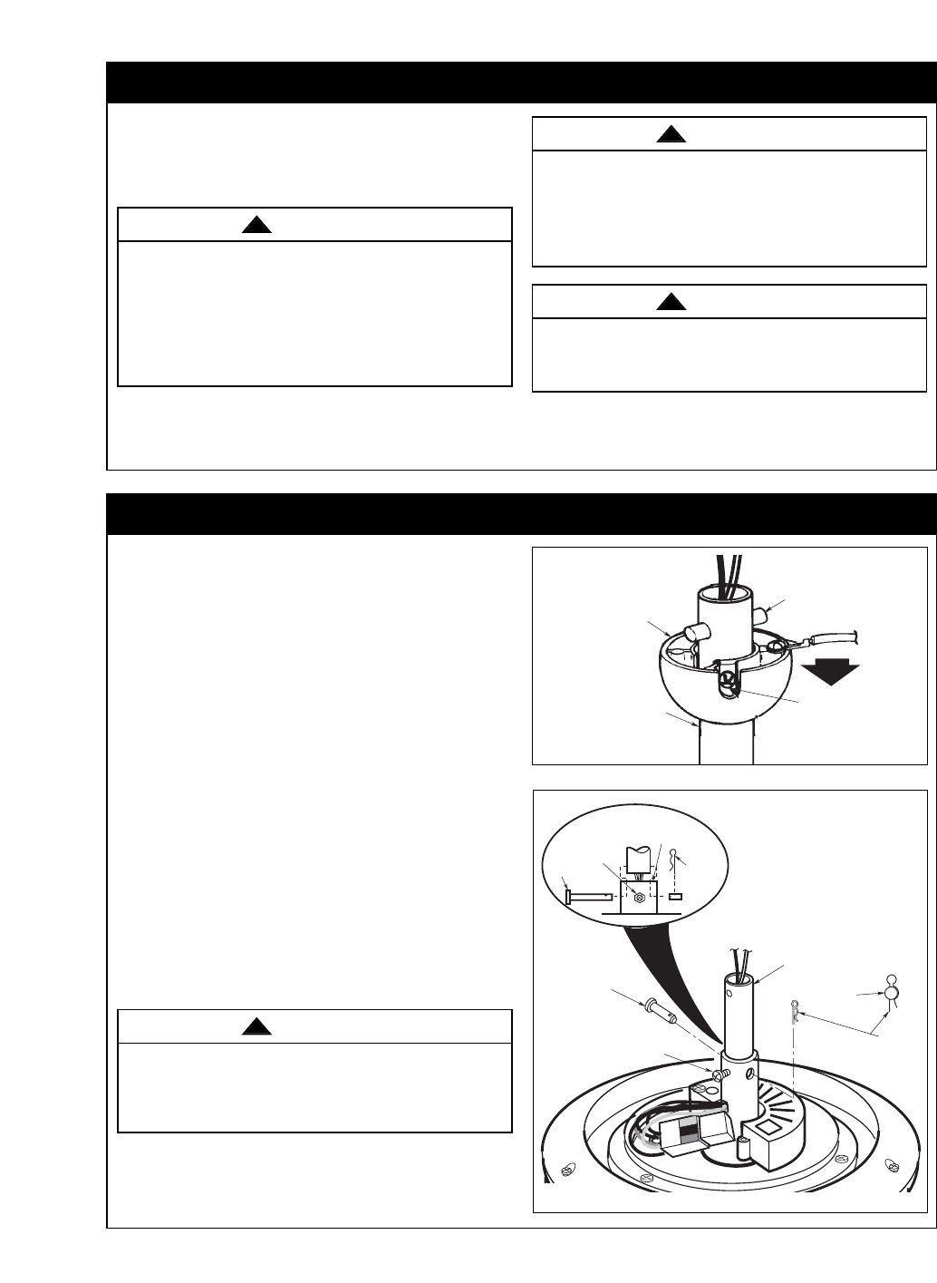
How to Put Your Ceiling Fan Together
UPPER
SETSCREW
DOWNROD
HAIRPIN
CLIP
MOTOR
COUPLING
SETSCREW
CLEVIS PIN
HAIRPIN
CLIP
CLEVIS
PIN
CLEVIS
PIN
Figure 2
PIN
SETSCREW
HANGER
BALL
DOWNROD
Figure 1
If your fan is to replace an existing ceiling light fixture,
turn electricity off at the main fuse box at this time and
remove the existing light fixture.
Your new ceiling fan will require a grounded electrical
supply line of 120 volts AC, 60 Hz, 15 amp circuit.
The outlet box must be securely anchored and
capable of withstanding a load of at least 50 pounds.
To avoid fire or shock, follow all wiring instructions
carefully. Any electrical work not described in these
instructions should be done or approved by a
licensed electrician.
Turning off wall switch is not sufficient. To avoid
possible electrical shock, be sure electricity is
turned off at the main fuse box before wiring. All
wiring must be in accordance with National and
Local codes and the ceiling fan must be properly
grounded as a precaution against possible electrical
shock.
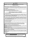
WARNING
!
WARNING
!
To reduce the risk of fire, electrical shock, or
personal injury, mount fan to outlet box marked
“Acceptable for Fan Support of 22.7 kg. (50 lbs.) or
less”, and use screws supplied with outlet box. Most
outlet boxes commonly used for support of light
fixtures are not acceptable for fan support and may
need to be replaced. Consult a qualified electrician if
in doubt.
WARNING
!
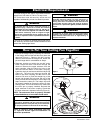
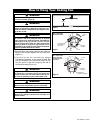
1. Remove the hanger ball by loosening the setscrew
in the hanger ball until the ball falls freely down the
downrod (Figure 1). Remove the pin from the
downrod, then remove the hanger ball. Retain the
pin and hanger ball for reinstallation in Step 4.
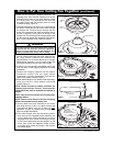
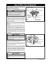
2. Separate, untwist and unkink the two 80” motor
leads. Route the motor lead wires through the
downrod. Remove the upper setscrew from the
motor coupling. Align the clevis pin holes in the
downrod with the holes in the motor coupling.
Install the clevis pin and secure with the hairpin clip
(Figure 2). The clevis pin must go through the
holes in the motor coupling and the holes in the
downrod. Be sure to push the straight leg of the
hairpin clip through the hole near the end of the
clevis pin until the curved portion of the hairpin clip
snaps around the clevis pin. The hairpin clip must
be properly installed to prevent the clevis pin from
working loose. Pull on the downrod to make sure
the clevis pin is properly installed. Reinstall the
upper setscrew in the motor coupling. Check that
the lower setscrew is tightened securely (Figure 2).
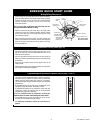
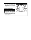
NOTE: The setscrews must be properly installed
as described above, or fan wobble could result.
NOTE: If LKU100 is being assembled, see Page
13, “Optional Accent Light Kit Installation” of
instruction procedures.
It is critical that the clevis pin in the motor coupling
is properly installed and the setscrews securely
tightened. Failure to verify that the pin and setscrews
are properly installed could result in the fan falling.
WARNING
!