


13
(RETAIN FOR LATER
INSTALLATION)
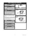
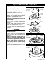
COUPLING COVER
SCREWS (3)
COUPLING
COVER
UPPER FAN
MOTOR
ASSEMBLY
Figure 16
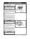
LIGHT KIT
ASSEMBLY
UPPER FAN MOTOR
ASSEMBLY
LIGHT KIT
ASSEMBLY
SCREW (3)
Figure 17
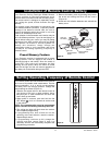
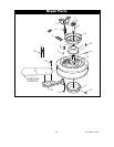
REINSTALL COUPLING
COVER SCREWS (3)
COUPLING COVER
Figure 19
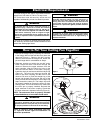
CAUTION: To reduce the risk of electric shock,
disconnect the electrical supply circuit to the fan
before installing light kit assembly.
1. Remove the three coupling cover screws and slide
the coupling cover up the downrod for installation
of light kit assembly (Figure 16). Retain the three
screws for later installation of coupling cover.
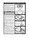
2. Position the light kit assembly so that the opening
of the light kit assembly slides through the
downrod. Align the mounting holes of the light kit
assembly to the motor assembly (Figure 17).
NOTE: Be sure the light kit assembly connector is
located close to the motor assembly connector for
ease of installation.
3. Install the light kit assembly to the motor assembly
using three light kit assembly mounting screws
(Figure 17).
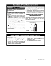
4. Securely connect the light kit assembly connector
to the motor assembly connector (Figure 18).
5. Screw the four 25-watt candelabra base bulbs
(supplied) into the light kit assembly sockets
(Figure 18).
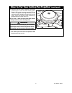
6. Carefully tuck all wiring and wire connectors close
to the downrod and slide the coupling cover over
the wires.
NOTE: Be sure light kit assembly wires are
positioned in the dimpled wireway of the upper
housing to avoid pinching of the wires during
installation of coupling cover.
CAUTION: Before installing and tightening the
screws, be sure there are no wires pinched
between the light kit assembly/motor assembly
and coupling cover.
7. Reinstall the three coupling cover screws to secure
the coupling cover (Figure 19).
Optional Accent Kit Installation
To avoid possible fire hazard, do not exceed four 25-watt
candelabra base light bulbs.
WARNING
!
LIGHT KIT ASSEMBLY
CONNECTOR
FAN MOTOR ASSEMBLY
CONNECTOR
25-WATT
CANDELABRA
BULB (4)
Figure 18
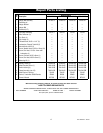
ETL Model No.: CF921