


9
U.L. Model No.: CF205
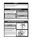
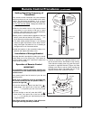
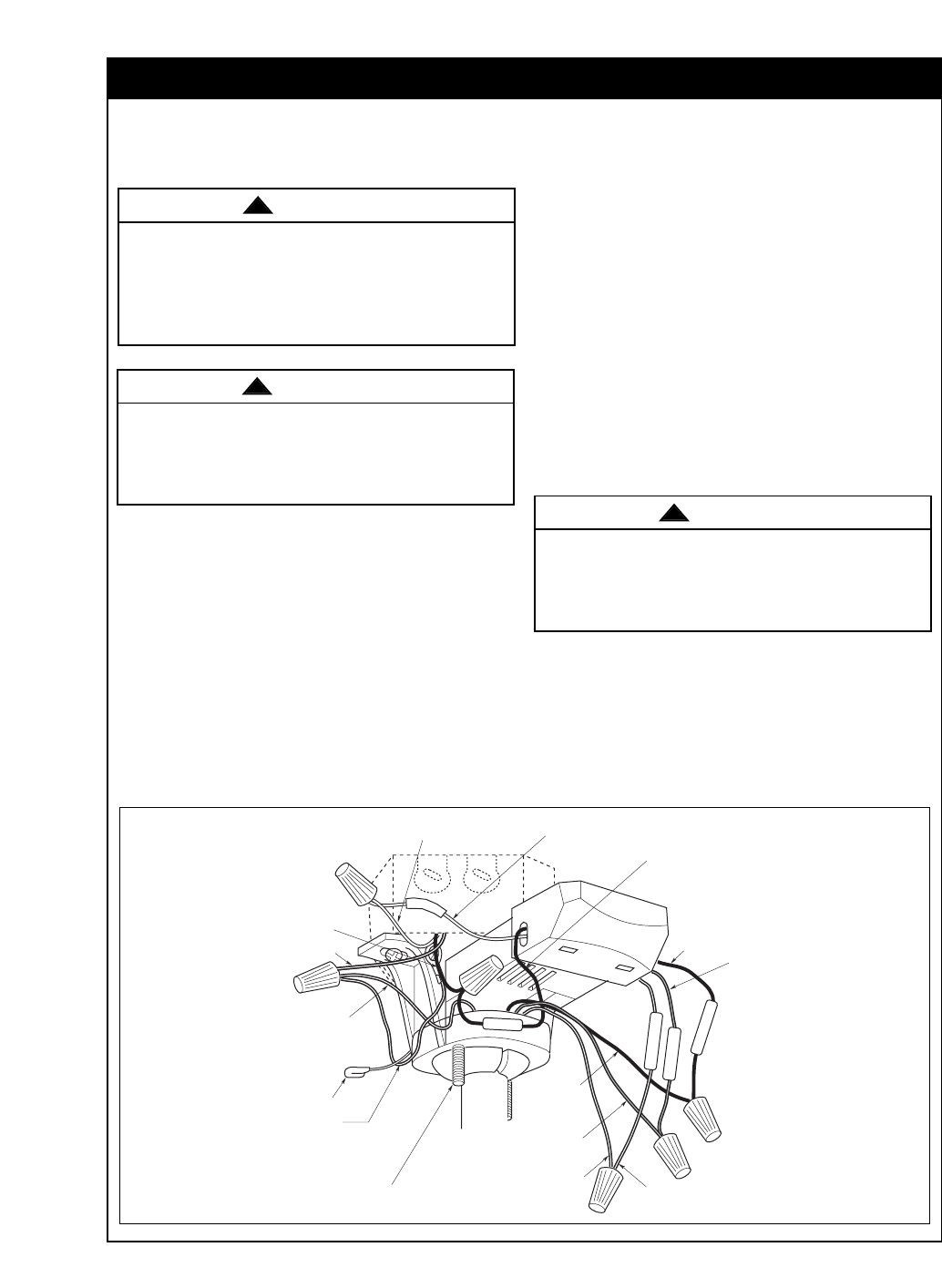
How to Wire Your Ceiling Fan
GREEN GROUND
WIRE FROM
HANGER BRACKET
RECEIVER RED WIRE
RECEIVER WHITE WIRE
FAN WHITE WIRE
FAN
BLACK
WIRE
ANTENNA
A
C
I
N
N
AC IN L
FOR LIGHT
TO MOTOR N
RECEIVER BLUE
WIRE
RECEIVER
BLACK WIRE
RECEIVER WHITE
WIRE
SUPPLY WHITE WIRE
(NEUTRAL)
SUPPLY BLACK
WIRE (HOT)
GROUND WIRE
GREEN GROUND
WIRE FROM
HANGER BALL
FAN BLUE WIRE
1-1/4" THREADED
STUD (2)
TO MOTOR L
Figure 14
If you feel that you do not have enough electrical
wiring knowledge or experience, have your fan
installed by a licensed electrician.
Turning off wall switch is not sufficient. To avoid
possible electrical shock, be sure electricity is
turned off at the main fuse box before wiring. All
wiring must be in accordance with National and
Local codes and the ceiling fan must be properly
grounded as a precaution against possible electrical
shock.
WARNING
!
To avoid possible electrical shock, be sure electricity
is turned off at the main fuse box before wiring.
NOTE: If you are not sure if the outlet box is ground-
ed, contact a licensed electrician for advice, as it
must be grounded for safe operation.
WARNING
!
CAUTION: To reduce the risk of electrical shock,
disconnect the electrical supply circuit before
installing the fan, light kit or receiver.
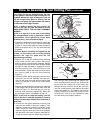
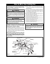
1. Position the supply wires to the left side of the out-
let box (Figure 14); position the fan wires to the
right side. Partially insert the remote control receiv-
er (flat side up) until one end rests on the hanger
ball as shown in Figure 14.
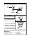
NOTE: Make all wiring connections using wire
connectors (supplied). Make sure that all connec-
tions are tight, including ground, and that no bare
wire is visible at the wire connectors, except for
the ground wire.
2. Refer to Figure 14 and 15 and connect the receiv-
er wires to the supply wires and the fan motor
wires as follows:
a. Securely connect the green grounding wires from
the hanger ball and the hanger bracket to the sup-
ply grounding conductor (this may be a bare wire
or a wire with green insulation).
b. Securely connect the supply white (neutral) wire to
the receiver white (AC IN N) wire.
c. Securely connect the supply black wire (hot) wire
to the receiver black (AC IN L) wire.
d. Securely connect the fan motor white wire to the
receiver white (TO MOTOR N) wire.
e. Securely connect the fan motor black wire to the
receiver red (TO MOTOR L) wire.
f. Securely connect the fan motor blue wire to the
receiver blue (FOR LIGHT) wire.
Check to see that all connections are tight, including
ground, and that no bare wire is visible at the wire
connectors, except for the ground wire. Do not oper-
ate fan until blades are in place. Noise and fan dam-
age could result.
WARNING
!