


4
U.L. Model No.: CF205
General
Your Emerson ceiling fan comes supplied with a
Fan/Light Remote Control which consists of a remote
control (transmitter) and a remote control receiver
mounted under the ceiling cover. This system allows
you to regulate your ceiling fan speed and light
intensity.
NOTE: An optional Emerson Electric SW406 Wall
Control may also be used to control your ceiling
fan.
Electrical Requirements
If your fan is to replace an existing ceiling light fixture,
turn electricity off at the main fuse box at this time and
remove the existing light fixture.
Your new ceiling fan will require a grounded electrical
supply line of 120 volts AC, 60 Hz, 15 amp circuit.
The outlet box must be securely anchored and capa-
ble of withstanding a load of at least 50 pounds.
To avoid fire or shock, follow all wiring instructions
carefully. Any electrical work not described in these
instructions should be done or approved by a
licensed electrician.
Turning off wall switch is not sufficient. To avoid
possible electrical shock, be sure electricity is
turned off at the main fuse box before wiring. All
wiring must be in accordance with National and
Local codes and the ceiling fan must be properly
grounded as a precaution against possible electrical
shock.
WARNING
!
WARNING
!
To reduce the risk of fire, electrical shock, or person-
al injury, mount fan to outlet box marked
“Acceptable for Fan Support”, and use screws sup-
plied with outlet box. Most outlet boxes commonly
used for support of light fixtures are not acceptable
for fan support and may need to be replaced.
Consult a qualified electrician if in doubt.
WARNING
!
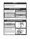
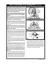
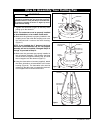
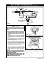
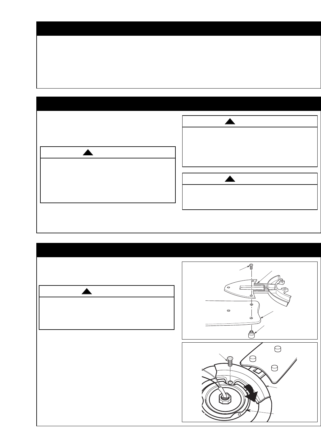
How to Assembly Your Ceiling Fan
1. Mount the fan blades to the blade flanges using
three 10-24 x 9mm oval head screws and three
decorative blade nuts (supplied) (Figure 1).
2. Remove and discard the three shipping retainers
securing the motor hub in the motor housing.
NOTE: Take care not to scratch the fan housing
when installing the blade assemblies.
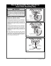
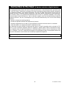
3. Rotate the motor hub to position the slot in the
motor plate over a fan motor/ housing flange hole.
Attach the blade flange assembly on the fan motor/
housing by slowly rotating the motor hub to align
screw holes. Tighten the screws securely while
interlocking the flange assemblies as you rotate the
hub (Figure 2).
To reduce the risk of personal injury, do not bend the
blade flange when installing the blade flanges, bal-
ancing the blades or cleaning the fan. Do not insert
foreign objects in between rotating fan blades.
WARNING
!
FAN BLADE
DECORATIVE
BLADE NUTS (3)
BLADE
FLANGE
10-24 X 9mm OVAL
HEAD SCREW (3)
Figure 1
1/4-20 x 11mm PAN HEAD
SCREW (2 per flange)
BLADE
FLANGE
MOTOR
HUB
Figure 2