


12
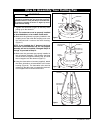
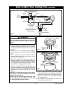
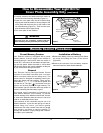
4. Carefully tuck blue and white wires from motor up
into the fan motor/housing assembly (Figure 21).
5. Place the cover plate onto the fan motor/housing
aligning the three flat areas on the top flange of the
cover plate with the three pins on the inside of the
fan motor/housing (Figure 21). Then turn the cover
plate clockwise until it stops turning.
6. Your cover plate is now installed.
How to Disassemble Your Light Kit for
Cover Plate Assembly Only (continued)
LIGHT KIT
PLATE
LIGHT KIT
COVER PLATE
FLAT AREA
LIGHT KIT PLATE
SOCKETS REMOVED
Figure 21
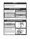
To avoid possible fire or shock, make sure that the
electrical wires are completely tucked inside the
lower assembly and not pinched by the cover plate.
WARNING
!
U.L. Model No.: CF205
Remote Control Procedures
Preset Memory Feature
Your Emerson receiver is equipped with a preset
memory feature. If the AC supply to the receiver is
powered through a wall switch, when the switch is
turned OFF, the control will remember the light inten-
sity and fan speed. When the switch is turned back
ON the light and fan will resume operation as they we
re prior to the switch being turned OFF.
General
Your Emerson Ceiling Fan/Light Remote Control
consists of hand-held transmitter and a receiver
which is mounted under the fan ceiling cover. The
remote control is designed to separately control your
ceiling fan speed and light intensity. There are four
push buttons (
.
,
..
,
...
,
....
) to set the fan speed and
turn the fan off. The light ( ) push button turns the
light on and off and controls the light intensity. The
blue indicator light will illuminate while any button is
pressed, indicating that the battery is good.
The remote control transmitter is powered by two
AAA alkaline batteries (not included). To prevent
possible damage if the batteries should leak, be sure
to remove the batteries when the control is not to be
used for an extended period of time.
Code switches in the transmitter may be set in 32
different positions. If your fan and light go on and off
without using your control, you may be getting
interference from other remote units such as garage
door openers, car alarms or security systems. To
remedy this situations, simply change the combina-
tion code in your transmitter.
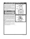
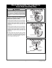
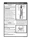
Installation of Battery
1.Remove the battery cover by pressing firmly below
the arrow and sliding the cover off the control
(Figure 22).
2.Remove the connector from the battery compart-
ment and install two AAA alkaline batteries.
CODE
SWITCHES
SR400 REMOTE
CONTROL
BATTERY
COMPARTMENT
COVER
TWO AAA
BATTERIES
REMOTE CONTROL
LEVERS
ON
1
234
5
I
Figure 22