


5
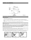
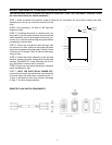
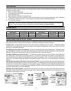
STEP 9: WITH THE ELECTRICAL POWER OFF, route
#14 gauge stranded copper wire from 12 VDC ground
and positive 12 VDC from the fuse panel through a 7- or
8-amp fuse or circuit breaker. Leave at least 30 inches
(305 mm) of wire for connecting to toilet (fig. 9).
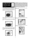
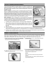
STEP 10: Connect the holding tank to the bottom of the
discharge flange.
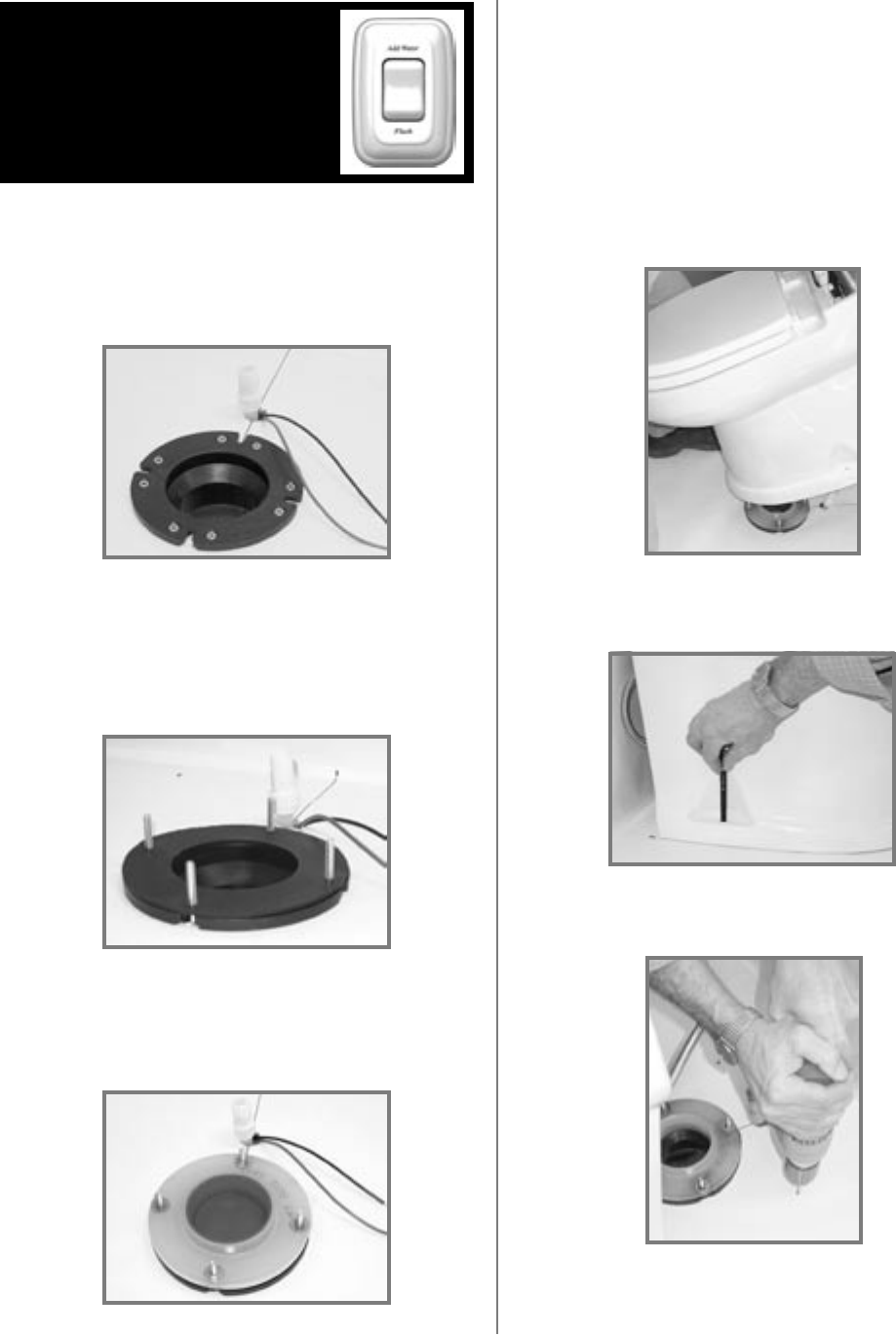
STEP 11: Slide the four T-bolts into the slots of the floor
flange. Install the flange gasket over the T-bolts (fig.
10).
Fig. 9
Fig. 10
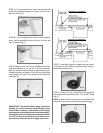
STEP 12: Install floor flange adapter with words “THIS SIDE
UP” facing up. Tighten adapter to floor flange using four
flat washers and hex nuts. Tighten in criss-cross pattern
(fig. 11).
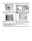
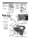
STEP 13: Temporarily set the toilet in place on the floor
flange (fig. 14).
STEP 14: Mark the holes for the two toilet mounting
bolts (fig. 15).
Fig. 16
STEP 15: Pick up toilet and set aside. Drill 3/16-inch
pilot holes in the floor (fig. 16).
Fig. 15
Fig. 14
Fig. 11
IMPORTANT: If replacing an existing toilet that uses
a 2-bolt floor flange, drill two 5/16-inch dia. holes in
old floor flange that align with two additional holes
in floor flange adapter. Use two #10 or 12 x 1-1/2-inch
wood screws and washers for these drilled holes,
and two T-bolts with flat washers and nuts to fasten
flange gasket and floor flange adapter to old floor
flange. Do not use old hardware or seal.
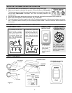
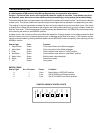
FOR MODEL 3400 TOILET
WITH REMOTE SWITCH
OPERATION, see page 7
for wall switch installation
instructions.