


6
3308120.XXX GENESIS AIR FILTRATION SYSTEM
5. The 14-1/4" (±1/8") opening is part of the return air
system of the air conditioner and must be finished in
accordance with NFPA Standard 501C Section 2.7.
C. AIR DISTRIBUTION DUCT INSTALLATION
Install the air distribution ducts in the RV roof cavity. The
distribution system must meet:
1. RV’s requirements
2. System requirements listed in Section 3 of this
Manual. Terminate the start of the duct at the back
edge of the 14-1/4" (±1/8") opening previously cut.
D. Place the Genesis Air Filtration System and System
Control Option inside the RV. These boxes contains
mounting hardware for the air conditioner/heat pump
and will be used inside the RV.
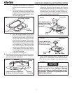
6. INSTALLATION OF UNIT
A. Take the Genesis Air Filtration System from the carton.
B. If the Controls are not part of the unit. Position the
electrical box towards the front of the opening with all of
the system control wires connected to the control box
except for the DC power. See figure 3.
Do not slide the unit. This may damage the
neoprene gasket attached to the bottom
and create a leaky installation.
CAUTION
This unit weighs approximately 100 pounds.
To prevent back injury, use a mechanical
hoist to place air conditioner/heat pump on
roof.
WARNING
!
C. Lift and place the unit over the prepared opening using
the gasket on unit as a guide. The roof gasket on the
bottom of the base pan goes toward the front of the RV.
Sliding the unit on the roof will damage the roof gasket.
Note: If center duct system is being used, be sure to
install duct adapter to the bottom of the base pan, before
unit is placed over opening. Duct adapter 3100342.XXX
and 3100262.XXX can be used. Alternate methods of
duct connection are available for installation; however,
they must be approved in writing by Dometic.
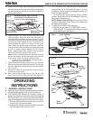
C. Locate the foam divider and insert it corner to corner in
the 14-1/4" x 14-1/4" (±1/8") opening with the adhesive
tape up (Do not remove paper to expose adhesive). The
foam divider should be level with the ceiling (±1/4"). Tear
off the excess at the pre-cut perforations in divider. See
figure 4.
NOTE: If using center duct installation See Step C-1. If
not center duct go to Step D.
Mark And Cut 8 x 2”
Opening For Center
Duct
FIG. 5
Foam
Divider
Tape Covered
Adhesive
1. Center Duct Installation (Penguin 620 & 630 Series
Only)
a. See Step B.
b. Cut notch in the center section of the foam
divider to fit duct (approximately 8 x 2
inches) . See figure 5.
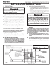
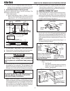
FRAME
14-1/4" (±1/8”)
OPENING
AC POWER
SUPPLY WIRE
DUCT
FRAME
DUCT
ROOF
INSULATION
DUCT
CEILING
DUCT
14-1/4" (±1/8”)
OPENING
INSULATION
SIDE VIEW
(TOWARD BACK OF RV)
TOP VIEW
(BACK OF RV)
LOW VOLTAGE WIRES:
12VDC
Furnace
Load Shed
Sensors
FRAME
CCC, CONTROL CABLE(S)
or 7-WireAnalog Cable
FIG. 2
5. PLACING THE UNIT ON THE ROOF
A. Remove the air conditioner/heat pump from the carton.
B. Place the air conditioner/heat pump on the roof.
FIG. 3
Vehicle
Front
Control
Box
Base
Pan
Wires Connected To
Control Box
FIG. 4
Place Foam Divider in
14-1/4" x 14-1/4" (±1/8")
Ceiling Opening Against
Base Pan Bottom
Ceiling
Upside
Down
Foam
Divider
Do not Peel Tape
Off Foam Divider
Base Pan
Foam Divider Ceiling
Level (±1/4") Tear Off
Excess