


5
3308120.XXX GENESIS AIR FILTRATION SYSTEM
D. REGISTER REQUIREMENTS AS FOLLOWS:
Min. Max.
1. Distance from Duct End 5" 8'
2. Distance from End of Elbow 15" —
3. Distance between Registers 24” —
4. Total Number Required 8 12
5. Min. No. required per Run 2 —
6. Min. Free Area per Register 14 sq. in. —
E. The Duct material must meet or exceed any agency
or RVIA Standard that may be in existence at the
time the RV is produced.
F. All Discharge Air Ducts must be properly insulated to
prevent condensation from forming on their surfaces or
adjacent surfaces during operation of the air conditioner/
heat pump. This insulation must be R-7 minimum.
G. Ducts and their joints must be insulated and sealed to
prevent condensation from forming on adjacent surfaces
during operation of the air conditioner/heat pump.
4. AIR DISTRIBUTION SYSTEM
INSTALLATION
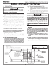
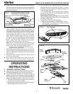
Dometic Corporation recommends the basic configuration
shown in FIG. 1 for installing this air conditioner/heat pump
system. We have found by testing, that this configuration
works best in most applications of this air conditioner/heat
pump system.
It is the responsibility of the Installer of this system to review
each RV floor plan and determine the following:
A. Duct size
B. Duct layout
C. Register size
D. Register locations
E. Thermostat location.
These items must be determined in conjunction with the Air
Distribution System Sizing and Design Requirements listed
in Section 3 of this manual.
Important: Alternate configurations and methods
may be used which still allow the air conditioner/heat
pump to operate properly. However, these alternate
configurations and methods must be approved by
Dometic Corporation in writing.
The following instructions are based upon the use of
Dometic Genesis Air Filtration System No. 3308120.XXX.
A. Before preparing the ceiling opening, the type of system
options must be decided upon. Read all of the instruc-
tions packaged with the system options before
beginning the installation.
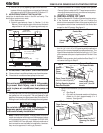
B. ROOF AND CEILING OPENING PREPARATION
1. A 14-1/4" x 14-1/4" (±1/8") opening must be cut
through the roof and ceiling of the RV. This opening
must be located between the roof and reinforcing
members.
C. DUCT SIZING REQUIREMENTS AS FOLLOWS:
NOTE: Duct sizes listed are inside dimensions.
Min. Max.
1. Duct Depth 2.00" 2-1/2"
2. Duct Width 8.00" 10.00"
3. Total Duct Length 15' 40'
4. Duct Length (Short Run) 1/3 Total Length
CENTER DUCT (Penguin 620 & 630 Series Only
Controls In Roof Package)
Min. Max.
1. Duct Depth 2.00" 2.00"
2. Duct Width 8.00" 8.00"
3. Total Duct Length 15' 40'
4. Duct Length (Short Run) 1/3 Total Length
H. Return Air to the air conditioner/heat pump must be
filtered to prevent dirt accumulation on air conditioner/
heat pump cooling surface.
I. Total System Static Air Pressure
This is to be determined with the air conditioner/heat
pump blower operating on High Speed and return air filter
and grill in place. It is measured in inches of water
Column.
0.55 - 0.90 In. W.C. 579 Series
0.40 - 1.10 In. W.C. 590, 591, 595 Series
0.12 - 0.65 In. W.C. 600, 630 Series
It is the responsibility of the installer to in-
sure the ductwork will not collapse or bend
during and after the installation. Dometic
Corporation will not be liable for roof struc-
tural or ceiling damage due to improperly
insulated, sealed or collapsed ductwork.
CAUTION
2. Mark a 14-1/4" x 14-1/4" (±1/8") square on the roof and
carefully cut the opening.
3. Using the roof opening as a guide, cut the matching
hole in the ceiling.
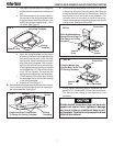
4. The opening created must be framed and sealed to
provide adequate support and prevent air from being
drawn from the roof cavity. Lumber 3/4" or more in
thicknessmust be used. Remember to provide an
entrance hole for power supplies and system wires as
needed.
WARNING
!
There may be electrical wiring between the
roof and the ceiling. Disconnect 115 volt AC
power cord and the positive (+) 12 volt DC
terminal at the supply battery. Failure to fol-
low this instruction may create a shock haz-
ard causing death or severe personal injury.