


Page 5
Installation
2841 E. Industrial Drive Springfield, MO 65802-6310 800-641-4282
XR10/XR20 Installation Guide
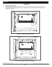
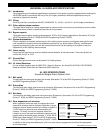
4.2 Mounting keypads
Security Command keypads have removable covers that allow you to easily mount the base with keypad circuit
board to a wall or other flat surface using the screw holes provided on each corner. Before mounting the base,
connect the keypad wire harness leads to the 4-wire keypad data bus cable from the panel. Next, attach the
keypad wire harness connector to the pin connector on the keypad circuit board, mount the base, and install the
keypad cover making sure all of the keys extend through their respective holes.
For mounting keypads on solid walls, or for applications where conduit is required, use a DMP 775, 776, or 778
keypad conduit backbox.
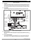
4.3 Wiring keypads
Keypad data bus
The keypad data bus consists of a 4-wire cable that provides 12 VDC power, data in, data out, and a panel
common. You can connect keypads in parallel on one 4-wire cable or provide a separate cable run back to the
panel for each keypad. The maximum cable length for one keypad can be up to 500 feet using 22 gauge wire or
up to 1000 feet using 18 gauge wire. Additional keypads installed on the same cable decrease the maximum
distance at which they'll operate properly.
Refer to the wiring diagram in this guide for additional wiring information. See section 3.2.
Primary Power Supply
5.1 AC terminals 1 and 2
Connect the transformer wires to terminals 1 and 2 on the panel. Use no more than 70 ft. of 16 gauge, or 40 ft. of
18 gauge, wire between the transformer and the XR10/XR20.
Always ground the panel before applying power to any devices:
The XR10/XR20 must be properly
grounded before connecting any devices or applying power to the panel. Proper grounding protects against
Electrostatic Discharge (ESD) that can damage system components. See Earth ground, section 6.2.
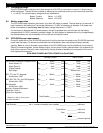
5.2 Transformer types
The standard transformer for the XR10/XR20 is 16.5 VAC 40VA, which provides up to 500mA of auxiliary current
and 100mA of smoke detector output. You can use either the Model 320 wire-in or 321 plug-in transformer with
the XR10/XR20. The total current available is limited by the total battery standby requirements of the installation.
The transformer must be connected to a 120 VAC 60 Hz commercial power outlet that is not controlled by a wall
switch. Never share the transformer output with any other equipment.
Secondary Power Supply
6.1 Battery terminals 3 and 4
Connect the black battery lead to terminal 4 on the panel and to the negative terminal of the battery. The
negative terminal connects to the enclosure ground internally through the XR10/XR20 circuit board. Connect the
red battery lead to terminal 3 on the panel and to the positive terminal of the battery. Observe polarity when
connecting the battery. The XR10 and XR20 panels can charge up to two batteries.
Use sealed lead-acid batteries
only:
Use the DMP Model 367, 12 VDC 6.5Ah sealed lead-acid rechargeable
battery. Batteries supplied by DMP or manufactured by Eagle Picher or Yuasa have been tested to ensure
proper charging with DMP products.
GEL CELL BATTERIES CANNOT BE USED WITH THE XR10/XR20 PANEL.
6.2 Earth ground
Terminal 4 of the XR10/XR20 panel must be connected to earth ground using 14 gauge or larger wire to provide
proper transient suppression. DMP recommends connecting to a metal cold water pipe or ground rod only. Do
not connect to electrical conduit or a telephone company ground.
6.3 Replacement period
DMP recommends the battery be replaced every 3 to 5 years under normal use.