


8 9
TUNDISH
The tundish supplied must be fitted visible to the occupier. The
discharge pipe must be 22mm copper pipe. Regulations do
not permit more than 3 x 90-degree bends between the
SCx
unit and the outflow. Between the temperature & pressure
relief valve and the first 90-degree bend there must be a fall
of at least 300mm. The fall of the pipework must be
continuous and the pipe should terminate in the gully or be
bent backwards onto an outside wall, in a place where
discharge cannot be injurious to persons.
If you need to site the
SCx unit In the middle of the house your
discharge pipe to the tundish can be as far away as 9m, which
in most cases is enough to run the final discharge point. After 9m,
increase the pipe size to a greater diameter than 22mm and
accordingly for subsequent 9m lengths, see table 1 on page 10.
COMMISSIONING THE SCx UNIT
Switch on electricity to the immersion heater(s) (Direct system)
or switch on the boiler (Indirect system). Refer to the boiler
manufacturers instructions on commissioning.
Bring the unit to its maximum temperature setting of approx.
60 degrees Celsius. You should, on operating the water taps,
have a good flow of hot and cold water assuming adequate
water is supplied to the
SCx unit.
Check the water does not discharge via the tundish pipework
during heating.
Recheck all fittings/joints for possible leaks.
On completion of the installation, before turning on the mains
water supply ensure that all residual materials are removed by
means of flushing the system with a suitable cleaner.
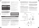
EXTERNAL EXPANSION VESSEL – OPTIONAL
This smaller tank is connected to the cold-water inlet side of
the vessel. Mount the tank according to separate manufacturers
instructions provided with the External Expansion vessel.
See fig 1 page 5.
SCALE
In hard water areas lower water temperatures can result in
less scale being deposited.
If water softener is used it should be capable of flows of
approx. 50 lt/min, this will maintain maximum performance
of the
SCx unit.
If no descaler or softener is used then the heating element(s)
will need descaling periodically for maximum efficiency.
DRAINING
Switch off electrical power to immersion heaters and/or shut
down the boiler. Close the stopcock valve to isolate the
SCx unit.
Attach hosepipe to the drain cock having sufficient length to
take water to a suitable discharge point.
Open drain cock
Open hot water tap nearest
SCx unit.
If water fails to drain from
SCx unit, vent the system by
opening the temperature pressure relief valve.
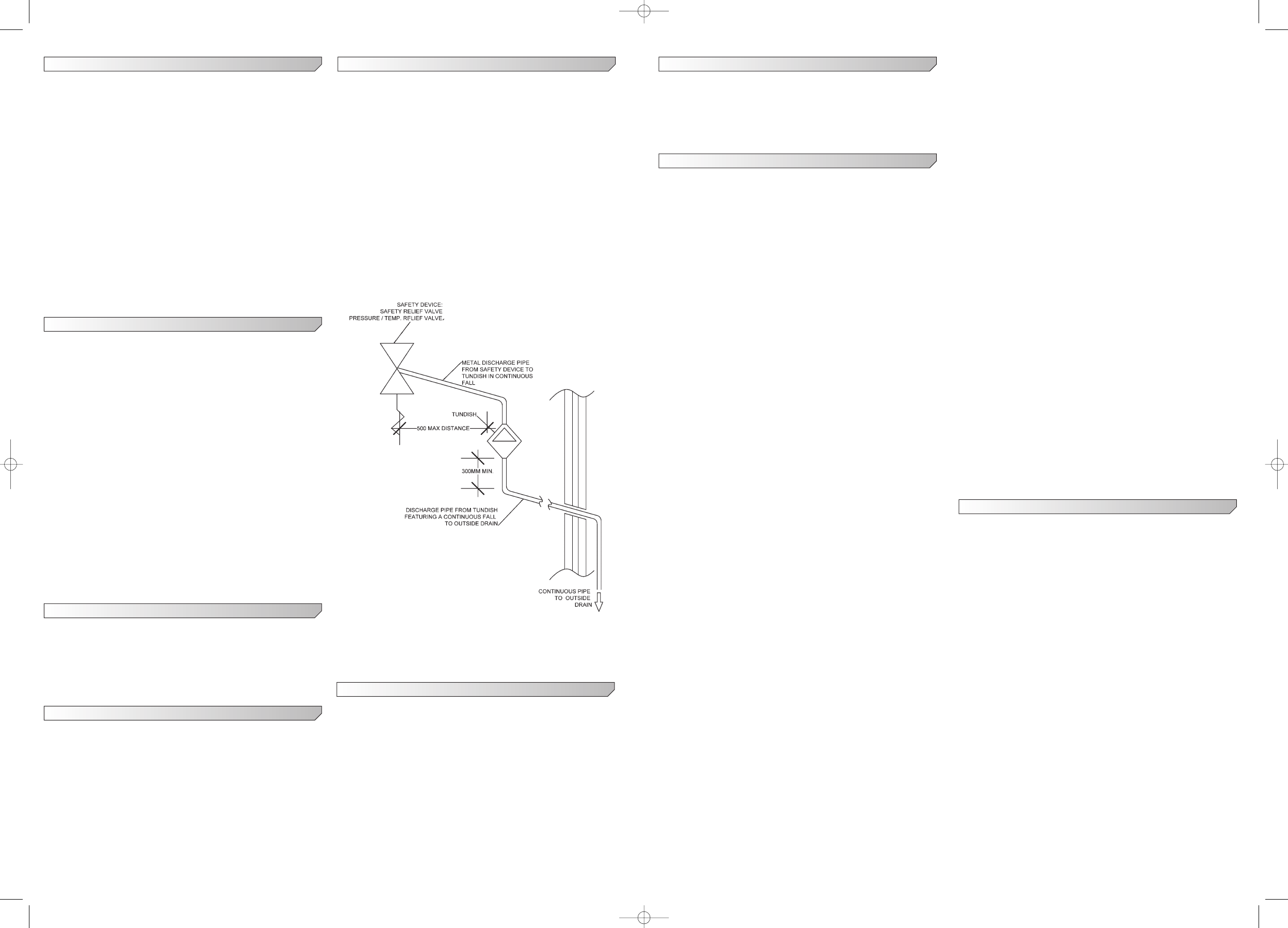
G3 REQUIREMENT
‘…there shall be precautions…to ensure that the hot water
discharged from safety devices is safely conveyed to where it is
visible but will not cause danger to persons in or about the building.’
G3 GUIDANCE SECTION 3.9
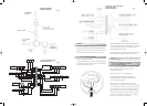
The discharge pipe (D1) from the vessel up to and including
tundish is generally supplied by the manufacturer of the hot
water storage system. Where otherwise the installation should
include the discharge pipe (s) (D1) from the safety device(s).
In either case the tundish should be vertical located in the
same space as the unvented hot water storage system and
be fitted as close as possible and within 500mm of the safety
device e.g the temperature relief valve.
The discharge pipe (D2) from the tundish should terminate in
a safe place where there is no risk to persons in the vicinity of
the discharge, preferably be of metal and:
a. be at least one pipe size larger than the nominal outlet size
of the safety device unless it’s total equivalent hydraulic
resistance exceeds that of a straight pipe 9m long ie.
discharge pipes between 9m and 18m equivalent resistance
length should be at least two sizes larger, than the nominal
outlet size of the safety device between 18 and 27m, at least
3 sizes larger and so on. Bends must be taken into account in
calculating flow resistance. Refer to Table 1 overleaf and fig. 6.
An alternative approach to sizing discharge pipes would
be to follow BS 6700:1987 specification for design
installation, testing and maintenance of services supplying
water for domestic use within buildings and their curtilages,
Appendix E, section E2 and table 21.
b. have a vertical section of pipe at least 300mm long, below
the tundish before any elbow or bends in the pipework.
c. be installed with a continuous fall.
d. have discharges visible at both the tundish and the final
point of discharge but where this is not possible or is
practically difficult there should be clear visibility at one or
other of these locations.
Examples of acceptable discharge arrangements are:
i) ideally below a fixed grating and above the water seal in
a trapped gully.
ii) downward discharges at low level; i.e. up to 100mm
above the external surfaces such as car parks, hard
standings, grassed areas etc. are acceptable providing
that where children may play or otherwise come into
contact with discharges a wire cage or similar guard is
positioned to prevent contact, whilst maintaining visibility.
iii) discharges at high level; e.g into a metal hopper and
metal down pipe with the end of the discharge pipe
clearly visible (tundish visible or not) or onto a roof
capable of withstanding high temperature discharges of
water and 3m from any plastics guttering system that
would collect such discharges (tundish visible.)
iv) where a single pipe serves a number of discharges, such as
in blocks of flats, the number served should be limited to not
more than 6 systems so that any installation discharging can
be traced reasonably easily. The single common discharge
pipe should be at least one pipe size larger than the largest
individual discharge pipe (D2) to be connected. If unvented
hot water storage systems are installed where discharges
from safety devices may not be apparent i.e. in dwellings
occupied by blind, infirm or disabled people, consideration
should be given to the installation of an electronically
operated device to warn when discharge takes place.
Note: The discharge will consist of scalding water and steam.
Asphalt, roofing felt and non-metallic rainwater goods may be
damaged by such discharges.
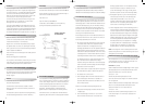
WORKED EXAMPLE OF DISCHARGE PIPE SIZING
The example below is for a G1/2 temperature relief valve with
a discharge pipe (D2) having 4 No elbows and length of 7m
from the tundish to the point of discharge.
From table 1: (overleaf)
Maximum resistance allowed for a straight length of 22mm copper
discharge pipe (D2) from G1/2 temperature relief valve is 9.0m
Subtract the resistance for 4 No 22mm elbows at
0.8m each = 3.2m
Therefore the permitted length equates to 5.8m
5.8m is less than the actual length of 7m therefore calculate
the next largest size.
Maximum resistance allowed for a straight length of 28mm pipe
(D2) from a G1/2 temperature relief valve equates to 18m
Subtract the resistance of 4 No 28mm elbows at
1.0m each = 4.0m
Therefore the maximum permitted length equates to 14m
As the actual length is 7m a 28mm (D2) copper pipe will
be satisfactory.
DISCHARGE PIPEWORK
It is a requirement of Building Regulations that any discharge
from an unvented system is conveyed to where it is visible, but
will not cause danger to persons in or about the building. The
tundish and discharge pipes should be fitted in accordance
with the requirements and guidance notes of Building
Regulations. Building Regulation G3 Requirements and
guidance section 3.9 reproduced in the following sections.
Information Sheet No. 33 available from the British Board of
Agreement gives further advice on discharge pipe installation.
SCHEMATIC DISCHARGE
PIPE ARRANGEMENT
Fig.6
Dimp-15278-SCx_Instructions 31/3/06 9:32 am Page 9