


6 7
WIRING
All electrical wiring should be carried out by a registered electrical
contractor and must conform to the latest IEE wiring regulations
Do not switch the power on until the unit has been filled with
water and all wiring has been earthed, see Fig. 4 and 5.
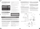
FITTING IMMERSION HEATERS
These are supplied as standard
An ’O’ ring is supplied as the seal and must be fitted against
the flange of the element. Take care not to cross thread and
DO NOT USE any other type of seal.
Fig.5
L
N
E
As our heating element is Incoloy 825 and is fitted with a cut-
out and thermostat for safety, a non-standard 1
3
/
4
" boss is fitted
to the unit. Replacements can only be obtained from your
authorised Dimplex Service Agent.
All our heating elements have a built in manual reset cut-out.
This will operate if the immersion heater thermostat fails.
WARNING: Ensure that the immersion heater thermostat is set
at 60 degrees Celsius.
FITTING THE THERMAL CUT-OUT &
PRIMARY CONNECTIONS
The motorised valve supplied and the thermal cut-out (Hi
limit stat) must be fitted to the primary flow. Use
compression fittings only.
Operation of the cut-out and motorised valve
To comply with BBA regulations and to prevent the
temperature reaching 100 degrees Celsius the thermal
cut-out supplied must be fitted.
The thermal cut-out is wired in series to the cylinder
thermostat. When the thermal cut-out senses an abnormal
rise in temperature in the primary flow the electrical supply
to the motorised valve will be cut, and the valve will be in
the closed position thus cutting of the primary water from
the boiler to the indirect coil in the cylinder. If this occurs it
must be reset manually. If the thermal cut-out operates
check the cylinder stat and / or boiler stat.
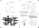
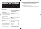
SECONDARY CIRCULATION
CONNECTION DIAGRAM
Fig.3
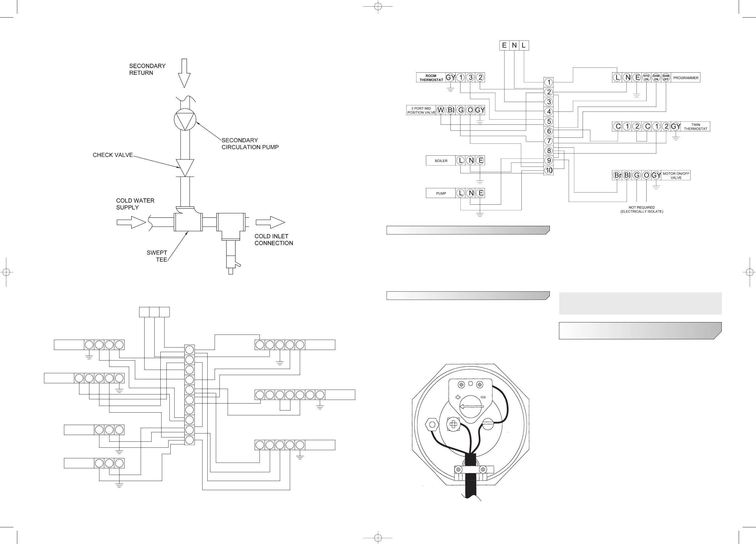
2 PORT VALVE + 3 PORT MID POSITION
VALVE (Y-PLAN) SYSTEM
GUIDANCE LAYOUT ONLY
1
2
3
4
5
6
7
8
9
10
Br
BI
GO
GY
132
Br BI
G
O
LN
E
HTG
ON
DHW
ON
PROGRAMMER
TWIN
THERMOSTAT
MOTOR ON/OFF
VALVE
PUMP
BOILER
2 PORT MID
POSITION VALVE
ROOM
THERMOSTAT
21
C
21
C
ENL
ENL
ENL
GY
GY
GY
2 * 2 PORT (S-PLAN) VALVE SYSTEM
GUIDANCE LAYOUT ONLY
Fig.4
Dimp-15278-SCx_Instructions 31/3/06 9:32 am Page 7