


4 5
CONNECTING THE WATER SUPPLY
● Pipework is not supplied
● All pipework should be installed using good plumbing
practice. We recommend 22mm mains cold water supply
is used.
● Install a Stop Cock Valve before the cold water inlet
assembly on the incoming mains water supply so the unit
can be isolated if required.
COLD WATER VALVE
The combined cold water valve (supplied) can be connected
anywhere on the cold water mains prior to the unit. It can even
be located at a point near to where the mains supply enters the
premises if this is more convenient. When installing the cold water
valve, ensure that the arrow is pointing in the same direction as
the mains water supply flow when connecting, see fig 2.
The cold water balancing port, on the valve, allows you to
connect the cold water mains to the rest of the property thus
giving balanced pressure throughout. If this facility is not
required leave the cap on.
DRAIN TAP
A drain tap to drain the unit must be fitted to the cold-water inlet
pipe somewhere between the
SCx unit and the cold water
valve assembly and at as low a level as possible, see fig. 1.
PIPEWORK TO TAPS
Ideally a 22mm pipe run should supply the outlets throughout
the property with short lengths (max 1 metre) runs of 15mm
going to baths, showers, and basin taps. Smaller bore pipe
can be used to suit taps.
SECONDARY CIRCULATION
This is particularly easy to fit on the SCx units; a Swept Tee (not
supplied) is needed for all indirect models if secondary
circulation is required, see page 6 fig. 3 for fitting. A non-return
valve (not supplied) must be fitted to prevent backflow. You
will need a pump to circulate the hot water (not supplied). The
return feed is in 15mm pipe and all work can be done on site.
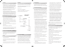
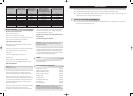
STANDARD ENERGY LOSSES
The heat loss of each SCx Unvented Unit while maintaining
the temperature of the stored water at 65 degrees Celsius.
(See performance table below).
1) Tests carried out by BBA. Slight variations may occur with
changes to water mains supply pressure
SITING THE SCx UNIT
The unit can be placed anywhere convenient. Because it is
connected directly to the mains water supply it is equally
efficient on any floor – ground, first or second. Avoid areas
that may be subject to frost. Try to keep pipe runs as short as
possible for maximum economy, especially hot water
discharge pipes running down from the
SCx unit.
The unit can be fitted into a conventional airing cupboard
and does not require any additional insulation.
ALL SCx UNITS MUST BE STORED VERTICALLY
CHECK WATER PRESSURE & FLOW RATES
We suggest 1.5 bar pressure & 15 litres / minute flow rate to
be the minimum requirements for satisfactory operation. Less
than this the unit will still operate but you will not be able to run
two, or more, outlets at the same time. 85% of all U.K homes
have more than 2-bar pressure.
The mains supply must not exceed 16 bar. If it does a special
pressure-reducing valve will be required.
Important Note: - Stainless Steel Tectile push fit elbows are
fitted as standard to all
SCx Cylinders.
Fig.1
Fig.2
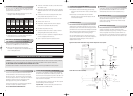
● 1 Element on IDH indirect models up to 305 litres and 80
litre DH direct model
● 2 Elements on DH direct models from 130 up to 305 litres.
Additional elements from 215 to 305 litres are available on
request.
● Cold-water control valve comprising line strainer, check
valve, pressure reducing valve set to 2.1 bar
● Expansion relief valve with non return valve set at 6 bar
● Tundish 15mm x 22mm F x F
● Temperature / Pressure relief valve set at 90 degrees
Celsius and 7 bar pressure relief (factory fitted)
● Motorised valve (indirect units only)
● Cylinder thermostat-factory fitted to cylinder, maximum
setting 85 degrees Celsius (indirect units only)
● Thermal cut out set to operate at 87 degrees Celsius plus
or minus 3 degrees (indirect units only)
● Option – Expansion vessel with capacity as below: -
Tank Size
80 to 130 Litres
150 to 215 Litres
255 to 305 Litres
Expansion Tank Required
12 Litres
18 Litres
25 Litres
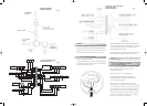
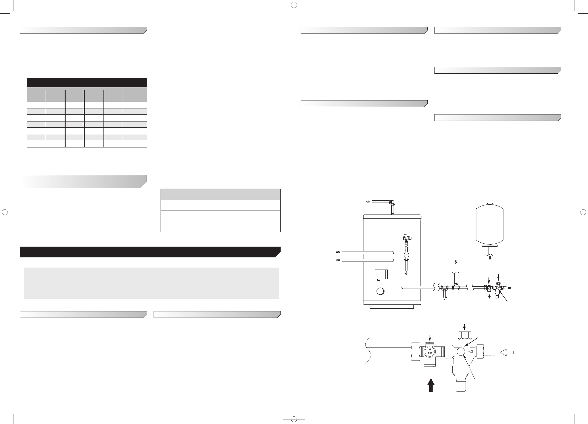
Typical Indirect Tank installation using external expansion vessel option
Cold water inlet valve assembly
PRESSURE REDUCING VALVE SET
AT 3 BAR
WATER FLOW INLET SIDE OF TANK
WATER FLOW FROM EXPANSION
TANK TO 22MM FEMALE THREAD BEHIND
COVER
BLANKED
PORT
2) These figures relate to a 45 degree differential between
the stored water and ambient temperature
WITH AN SCx UNVENTED CYLINDER THE
FOLLOWING IS SUPPLIED AS STANDARD
Before commencing installation check that all the
components of your
SCx Unit are contained in the kit.
● 3KW Incoloy 825 heating element-incorporating
thermostat to 70 degrees Celsius and resetable safety cut
out set at 80 degrees Celsius
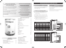
SCx UNVENTED INSTALLATION INSTRUCTIONS
WARNING: Under no circumstances must the factory fitted temperature pressure relief valve be removed. This will totally invalidate
any guarantee or claim. The cold-water inlet valve assembly must be fitted or the SCx unit will not perform satisfactorily.
DO NOT ATTEMPT TO VENT THE PRIMARY CIRCUIT THROUGH THE SCx UNIT.
All boilers should be installed to manufacturers instructions and the primary circuit through the SCx unit must be pumped.
WATER FLOW
HOT WATER OUTLET
PRIMARY FLOW
PRIMARY RETURN
TWIN
THERMOSTAT
IMMERSION
HEATER
WATER FLOW
TO COIL INLET
WATER FLOW
FROM COIL INLET
7 BAR / 90 DEGREES
PRESSURE &
TEMPERATURE
RELIEF VALVE.
TUNDISH
WATER FLOW
TO OVERFLOW
WATER INLET
DRAIN
COCK
SECONDARY
RETURN FLOW
SWEPT TEE
EXPANSION VESSEL
(WALL MOUNTED)
WATER FLOW TO
MANIFOLD VIA
FLEXIBLE HOSE
6 BAR
EXPANSION
RELIEF
VALVE
PRESSURE
REDUCING VALVE
SET AT 3 BAR
WATER FLOW
INLET SIDE OF TANK
BLANKED
PORT
WATER FLOW
FROM EXPANSION
TANK TO 22MM
FEMALE THREAD
BEHIND COVER
6 BAR
EXPANSION
RELIEF
VALVE
BALANCED
COLD WATER
OUTLET
SCx Performance
Nominal Heat up Heat up Reheat Reheat Heat loss in
Capacity Model IDH Model DH Model IDH Model DH 24 hrs
Litres Mins Mins Mins Mins kw/hr
80 33 64 23 53 1.12
130 28 115 21 90 1.50
150 33 138 24 104 1.82
175 27 167 24 124 2.10
215 35 212 30 153 2.64
255 42 263 35 184 2.73
305 50 313 42 220 2.88
Dimp-15278-SCx_Instructions 31/3/06 9:32 am Page 5