


www.dimplex.de E-5
English
8.3
For more detailed instructions concerning the connection and
functioning of the heat pump controller (e.g. the supplied external
wall sensor) please refer to the enclosed operating manual of the
controller.
An automatic circuit-breaker with simultaneous tripping of all ex-
ternal conductors is to be provided in the load power supply. The
circuit-breaker must be an all-pole disconnect device with a con-
tact gap of at least 3 mm. The same applies to any additional dis-
able contactors that may be required, e.g. during shut-off periods
imposed by the utility company. The required cross-sectional
area of the conductors is to be selected according to the power
consumption of the heat pump, the technical connection require-
ments of the relevant utility company and all applicable regula-
tions. Power consumption data of the heat pump is provided in
the product literature and on the nameplate. The terminals are
designed for a max. conductor cross-section of 35 mm².
ATTENTION!
The clockwise phase sequence must be observed when connecting the
load lines (the heat pump will deliver no output and will be very noisy
when the phase sequence is incorrect).
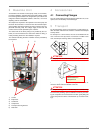
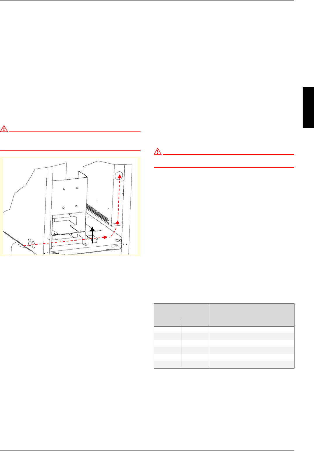
The power cable must be run through the guide tubes, inserted
into the side of the control box and secured by means of the
strain relief.
8 Commissioning
8.1 General Information
To ensure proper commissioning it should be carried out by a
customer service authorised by the manufacturer. This will lead,
under certain circumstances, to an extension of the warranty pe-
riod (cf. Warranty).
8.2 Preparatory Steps
Prior to commissioning, the following items need to be checked:
All connections of the heat pump must have been made as
described in Chapter 7.
The heat source system and the heating circuit must have
been filled and checked.
The strainer must have been fitted in the sole inlet of the
heat pump.
In the brine and heating circuits all valves that might impair
the proper flow must be open.
The settings of the heat pump controller must be adapted to
the heating installation in accordance with the instructions
contained in the controller's operating manual.
8.3 Commissioning Procedure
The start-up of the heat pump is effected via the heat pump con-
troller.
ATTENTION!
Commissioning is to be effected in accordance with the installation and
operating manual of the heat pump controller.
Where an overflow valve is fitted to assure the minimum heating
water flow rate, the valve must be set in accordance with the re-
quirements of the heating installation. An incorrect setting may
result in various error symptoms and an increased elec-tric
power consumption. To correctly set the overflow valve, the fol-
lowing procedure is recommended:
Close all of the heating circuits which may also be closed during
operation (depending on the type of heat pump usage) so that
the least favourable operating state - with respect to the water
flow rate - is achieved. Normally, these heating circuits are those
of the rooms located on the south and west sides of buildings. At
least one heating circuit must remain open (e.g. bathroom).
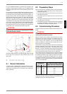
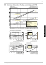
The overflow valve is to be opened to such an extent that based
on the current heat source temperature the maximum tempera-
ture difference between heating supply and return flow tempera-
ture is obtained, as indicated in the table below. The tempera-
ture difference should be measured as closely to the heat pump
as possible. In mono-energetic systems, the electric heating ele-
ment is to be deactivated.
Any malfunctions occurring during operation are displayed on the
heat pump controller and can be corrected as described in the
operating manual of the heat pump controller.
Heat source
temperature
max. difference between heating
supply and return temperature
from to
-5° C 0° C 10 K
1° C 5° C 11 K
6° C 9° C 12 K
10° C 14° C 13 K
15° C 20° C 14 K
21° C 25° C 15 K