


7
CAUTION!
MOUNTING
pump installations where a power failure cannot
readily be detected (e.g. holiday houses), the heating
circuit must contain a suitable antifreeze product.
The integrated expansion vessel has a capacity of
24 litres.This capacity is appropriate for buildings
with a heated living space floor area of up to 200 m
2
.
The planner of the heating system should verify that
the capacity of the expansion vessel is adequate. An
additional expansion vessel may have to be
installed, if required (as per DIN 4751 Part 1). Charts
in manufacturer catalogues facilitate the proper
selection of the proper size according to the amount
of water in the system.
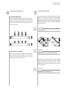
With large-capacity heating circuits,
the installed expansion vessel (24 litres, 1.0 bar
admission pressure) must be supplemented by
an additional vessel.
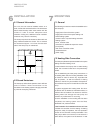
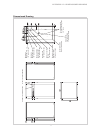
7.3 Connection on Heat Source Side
The following procedure must be observed when
making the connection:
Connect the brine line to the flow and return pipe
of the heat pump. The supplied strainer and vent
must be field-installed in the brine inlet of the heat
pump.
The powerful vent must be installed at the highest
point of the heat source system
The hydraulic block schematic must be taken into
account when so doing.
The brine liquid must be produced prior to charging
the system. The brine concentration must be at least
25 %. Freeze protection down to -14 °C can thus be
ensured.
Only antifreeze agents on a monoethylene glycol or
propylene glycol basis are to be used.
The heat source system has to be vented and leak-
tested.
The brine solution must contain at
least 25 % of an antifreeze and corrosion protection
agent on a monoethylene glycol or propylene glycol
basis.
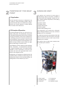
7.4 Electrical Connection
The following electrical connections must be
established on the heat pump.
- Connection of the load wire to the control panel
of the heat pump.
- Connection of the control voltage wire to the
control panel of the heat pump.
All electrical components required for the operation
of the heat pump are located on the control panel..
For detailed instructions concerning the connection
of external components and the operation of the heat
pump controller refer to the heat pump terminal dia-
gram and the operating manual of the controller.
Connection of the load wire to the control panel via
terminals X1: L1/L2/L3/PE.
An all-pole disconnecting device with a contact gap
of at least 3 mm (e.g. utility company disable contac-
tor or power contactor) as well as a 3-pole circuit
breaker with simultaneous tripping of all external
conductors must be provided . The required cross-
sectional area of the conductor is to be selected
according to the power consumption of the heat
pump, the technical connection requirements of the
relevant utility company and all applicable regula-
tions. Power consumption data of the heat pump is
provided in the product literature and on the
nameplate. The terminals are designed for a max.
conductor cross-section of 10 mm˝.
The clockwise phase sequence
must be observed when connecting the electric
load lines (in the case of an incorrect phase
sequence the heat pump will deliver no output
and generate a lot of noise).
Connection of the control voltage wire is effected via
terminals X1: L/N/PE.
If a more powerful brine pump is required than the
one integrated, a motor contactor and an appropriate
motor protecting switch need to be installed. The
contactor must be connected to the terminals of the
internal brine pump (controller terminals J12/N03
and X1-N). The power supply of the larger pump
must be provided by the mains supply.
CAUTION!
CAUTION!