


20
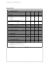
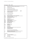
12.4.4 Legend .. 7KS to .. 14KS
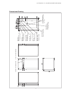
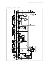
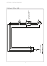
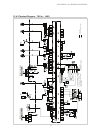
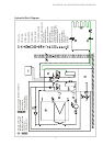
APPENDIX: 12.4 WIRING DIAGRAMS
A1 Wire jumper, must be inserted if no utility company disable contactor is required
A2 Wire jumper, must be removed if 2nd disable input is used
B3* Thermostat, hot water
B4* Thermostat, swimming pool water
E9* Electric immersion heater, hot water
E10* Back-up heater (boiler or electric heating element)
F2 Load fuse for N1 relay outputs across J12 and J13 4,0 ATr
F3 Load fuse for N1 relay outputs across J15 to J18 4,0 ATr
F4 Pressostat, high pressure
F5 Pressostat, low pressure
H5* Lamp, remote fault indicator
J1...J18 Terminal connectors at N1
K1 Contactor, compressor
K11* Electron. relay for remote fault indicator (on relay module)
K12* Electron. relay for swimming pool water circulating pump (on relay module)
K20* Contactor, back-up heater
K21* Contactor, electr. immersion heater, hot water
K22* Utility company disable contactor
K23* SPR auxiliary relay
M1 Compressor
M11 Primary circulating pump (brine)
M13 Heating circulating pump
M15* Heating circulating pump, heating circuit 2
M16* Suppl. circulating pump
M18* Hot water circulating pump
M19* Swimming pool water circulating pump
M21* Mixer, primary circuit
M22* Mixer, heating circuit 2
N1 Heat pump controller
N7 Soft starter
N10* Remote control station
N11* Relay module
R1 External sensor
R2 Return sensor
R3 Hot water sensor (as an alternative to the hot water thermostat)
R5 Sensor for heating circuit 2
R6 Freeze protection sensor
R7 Coding resistor 8.2 kOhm
T1 Safety isolating transformer 230/24 VAC-28VA
X1 Terminal strip, mains-load 3L/PE-400 VAC-50 Hz/
Mains-control L/N/PE-230 VAC-50Hz / fuses/N- and PE-terminal block
X2 Terminal strip 24 VAC-terminal block
X3 Terminal strip GND terminal block for analog inputs at J2 and J6
Abbreviations:
EVS Utility company disable input
SPR Supplementary disable input, configurable
MA* Mixer OPEN
MZ Mixer CLOSED
* Components to be supplied by the customer