


9
Remove top panel.3.
Locate the upper light on/off switch mounted on the 4.
rear panel and disconnect the wiring clips and connec-
tions noting their original locations.
Depress the retainer clips on the rear of the switch and 5.
push the switch out of the rear cover.
Properly orient the new switch and connect all of the 6.
wiring clips and connections.
Reassemble in the reverse order as above.7.
TO REPLACE FLAME MOTOR/FLAME
ROD
WARNING: If unit was operating prior to servicing
allow at least 10 minutes for light bulbs and heating ele-
ment to cool off to avoid accidental burning of skin.
WARNING: Disconnect power before attempting any
maintenance or cleaning to reduce the risk of electric
shock or damage to persons.
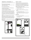
Gently place stove on its back on a at surface.1.
Remove the heater cover retaining screws located on 2.
the bottom of the stove and lower heater and light as-
sembly out onto the oor.
Remove all of the mounting screws on the heater cover 3.
and separate the cover from the heater and light as-
sembly.
Locate the ame motor and ame rod assembly and 4.
remove the wiring clips and connections located by the
heater assembly noting their original locations.
Remove the ame motor mounting screws and discon-5.
nect the ame motor from the ame rod.
!
NOTE: When removing the ame motor some dam-
age may occur to the ame rod. If ame rod is damaged
replace to insure proper operation.
Reassemble in the reverse order as above.6.
TO REPLACE HEATER ON/OFF
SWITCH
WARNING: If unit was operating prior to servicing
allow at least 10 minutes for light bulbs and heating ele-
ment to cool off to avoid accidental burning of skin.
WARNING: Disconnect power before attempting any
maintenance or cleaning to reduce the risk of electric
shock or damage to persons.
Remove back panel screws located along the rear of 1.
the top panel.
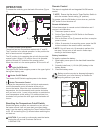
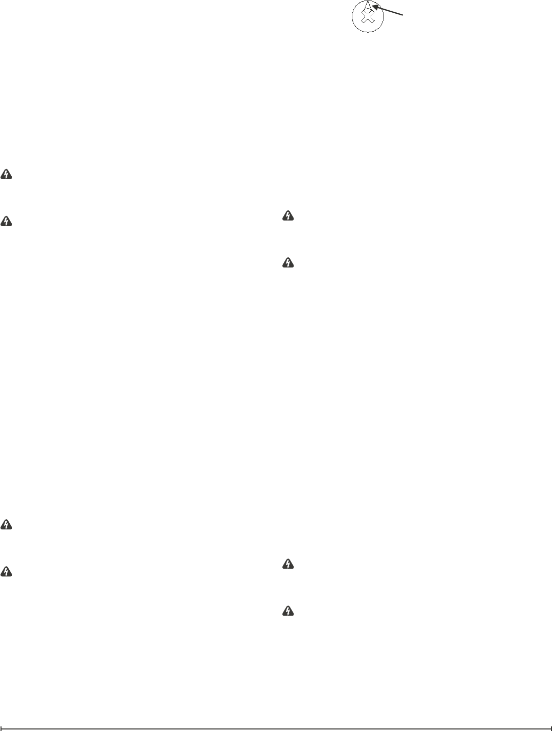
Open front door and release the Cams located in the 2.
upper corner of both side panels.
!
NOTE: To release Cams ensure arrow on Cam is fac-
ing up.
arrow
Remove top panel.3.
Locate the heater on/off switch mounted on the rear 4.
panel and disconnect the wiring clips and connections
noting their original locations.
Depress the retainer clips on the rear of the switch and 5.
push the switch out of the rear cover.
Properly orient the new switch and connect all of the 6.
wiring clips and connections.
Reassemble in the reverse order as above.7.
TO REPLACE HEATER THERMOSTAT
CONTROL
WARNING: If unit was operating prior to servicing
allow at least 10 minutes for light bulbs and heating ele-
ment to cool off to avoid accidental burning of skin.
WARNING: Disconnect power before attempting any
maintenance or cleaning to reduce the risk of electric
shock or damage to persons.
Gently place stove on its back on a at surface.1.
Remove the heater cover retaining screws located on 2.
the bottom of the stove and lower heater and light as-
sembly out onto the oor.
Remove all of the mounting screws on the heater cover 3.
and separate the cover from the heater and light as-
sembly.
Locate the thermostat mounted to the heater cover and 4.
disconnect the wiring connections noting their original
locations.
Pull off the thermostat control knob to expose the 5.
mounting screws.
Remove the mounting screws and remove the heater 6.
thermostat control switch.
Properly orient the new heater thermostat control and 7.
connect all of the wiring connections.
Reassemble in the reverse order as above.8.
TO REPLACE HEATER ASSEMBLY
WARNING: If unit was operating prior to servicing
allow at least 10 minutes for light bulbs and heating ele-
ment to cool off to avoid accidental burning of skin.
WARNING: Disconnect power before attempting any
maintenance or cleaning to reduce the risk of electric
shock or damage to persons.
Gently place stove on its back on a at surface.1.
Remove the heater cover retaining screws located on 2.
the bottom of the stove and lower heater and light as-
sembly out onto the oor.
Remove all of the mounting screws on the heater cover 3.