


E-6
English
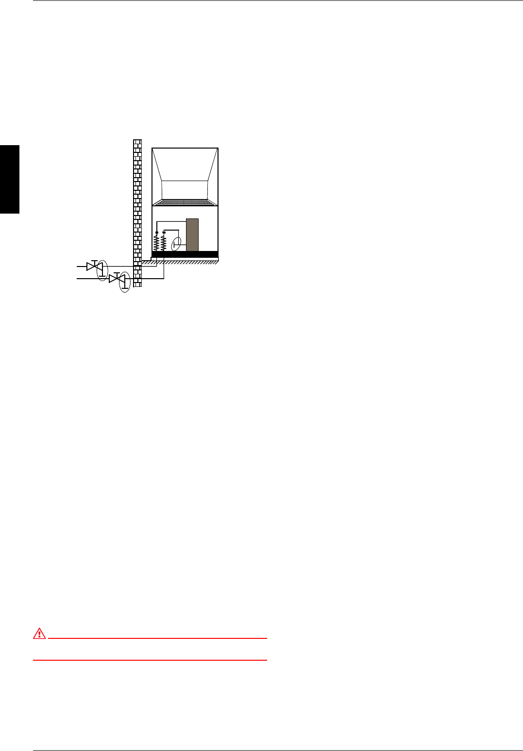
6.3
Antifreeze
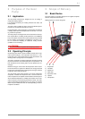
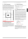
Manual drainage should be provided for heat pumps which are
exposed to frost. The antifreeze function of the heat pump con-
troller is active whenever the controller and the heat circulating
pump are ready for operation. If the heat pump is taken out of
service or in the event of a power failure, the system has to be
drained, and if required, blown out, at three locations (see illus-
tration). The heating circuit should be operated with a suitable
antifreeze if heat pump systems are implemented in buildings
where a power failure can not be detected (holiday home).
6.3 Electrical Connection
A standard four-core cable is used for connecting the heat pump
to the power supply.
The power supply and the control line are normally installed in
the ground (in ductwork with a suitable size and resistance) and
routed from the heat pump to the building. This ductwork must
extend into the heat pump by approx. 22 mm and be installed
with a continuous downward slope in order to comply with Sec-
tion 42 of the VDE 0100 regulations. Instead of 90° bends, two
45° bends must be used as pipe bends. The control line and the
cable for the power supply are drawn into this ductwork.
The cable (power supply) must be provided by the customer. The
conductor cross section is selected in accordance with the power
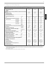
consumption of the heat pump (see Appendix Device Informa-
tion) and the applicable VDE (EN) and VNB regulations.
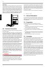
The power supply line on the heat pump must be fed through the
provided cable feedthrough into the switch box. The line must be
firmly screwed to its feedthrough (vapour sealed pipe union).
An all-pole disconnecting device with a contact gap of at least
3 mm (e.g. utility blocking contactor or power contactor) as well
as a 3-pole circuit breaker with common tripping for all external
conductors must be installed in the power supply (tripping current
in compliance with the Device Information). Ensure that the in-
coming supply has a clockwise rotating field when connecting
multiphase devices.
Phase sequence: L1, L2, L3.
ATTENTION!
Ensure that there is a clockwise rotating field: Operating the compressor
in the wrong rotational direction could cause damage to the compressor.
The control voltage is supplied via the heat pump controller.
The heat pump controller has a 230 V AC-50 Hz power supply.
Connect the controller in compliance with its own operating in-
structions (16 A fuse).
The control line (not included in scope of supply) is connected to
the heat pump controller using the two rectangular plug connec-
tors and the single-core wire. The plug connector is located on
the bottom side of the switch box inside the heat pump. More de-
tailed information can be found in the operating instructions of
the heat pump controller.
For detailed information, see Circuit Diagrams in the Appendix.
7 Start-up
7.1 General Information
To ensure that start-up is performed correctly, it should only be
carried out by an after-sales service technician authorised by the
manufacturer. This may be a condition for extending the guaran-
tee (see Warranty).
7.2 Preparation
The following items need to be checked prior to start-up:
The heat pump must be fully connected, as described in
Chapter 6.
All valves that could impair the proper flow of the heating
water in the heating circuit must be open.
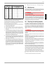
The air intake and air outlet paths must be clear.
The ventilator must turn in the direction indicated by the ar-
row.
The settings of the heat pump controller must be adapted to
the heating system in accordance with the controller’s oper-
ating instructions.
Ensure the condensate outflow functions properly.
7.3 Procedure
The heat pump is started up via the heat pump controller. Adjust-
ments should be made in compliance with the instructions.
If an overflow valve is fitted to assure the minimum heating water
flow rate, the valve must be set in accordance with the require-
ments of the respective heating system. Incorrect adjustment
can lead to faulty operation and increased energy consumption.
We recommend carrying out the following procedure to correctly
adjust the overflow valve:
Close all of the heating circuits that may also be closed during
operation (depending on the type of heat pump usage) so that
the most unfavourable operating state - with respect to the water
flow rate - is achieved. This normally means the heating circuits
of the rooms on the south and west sides of the building. At least
one heating circuit must remain open (e.g. bathroom).
The overflow valve should be opened far enough to produce the
maximum temperature spread between the heating flow and re-
turn flow listed in the following table for the current heat source
temperature. The temperature spread should be measured as
close as possible to the heat pump. The heating element of mono
energy systems should be disconnected.