


E-4
English
3.2
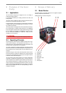
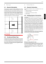
3.2 Switch Box
The switch box is located in the heat pump. All electrical compo-
nents are accessible after the front cover and the switch box
cover have been removed.
The switch box contains the supply connection terminals, the
plug connector for the control line, as well as the power contac-
tors and the soft starter unit.
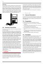
3.3 Heat Pump Controller
Use the heat pump controller included in the scope of supply to
operate the air-to-water heat pump.
The heat pump controller is a convenient electronic regulation
and control device. It controls and monitors the entire heating
system on the basis of the external temperature, including do-
mestic hot water preparation and safety systems.
The customer must install the return temperature sensor and the
external temperature sensor, which are supplied with the heat
pump controller / with these instructions together with the neces-
sary fixing accessories.
The operating instructions included in the scope of supply of the
heat pump controller describe its function and use.
4 Transport
ATTENTION!
Never install the device in rooms in which there are any permanent
ignition sources.
ATTENTION!
When transporting the heat pump, ensure that it is not tilted more than
45° (in any direction).
The heat pump should be transported to its final installation loca-
tion packaged and using the wooden pallet. The device can be
transported to its final location e.g. with a lift truck or one or two
hand trucks.
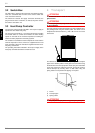
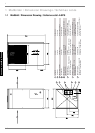
The devices LA 12PS and LA 18PS are packaged with transport
pipes on the wooden pallets. These pipes can be inserted using
the boreholes of the heat pump base frame (they are sealed with
cover caps, which can easily be removed), and can be used for
manual transport by securing them on both sides using the
spring cotters to keep them from slipping out of place.
1) Frame
2) Transport pipe
3) Spring cotters
ATTENTION!
The heat pump and transport pallet are only joined by the packing film.