


www.desatech.com
119939-01A
3
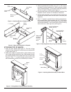
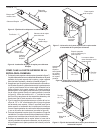
ATTACHING TOP OF MANTEL
1. Place top onto mantel (see Figure 7). The rear of legs
shouldbeushwithbackofmanteltopandcenteredleft
to right (see Figure 7).
2. Make sure mantel is centered left to right inside top and
rearoflegsareushwithbackoftop.Gapbetweenmantel
top and leg should be the same from front to back (see
Figure 8). Use 1
1
/
4
" screws through pocket holes in the
side assemblies and the front to attach top of mantel.
Figure 7 - Placing Mantel Top Onto Mantel Assembly
Mantel
Top
Leg
Assembly
Header
Legs Should Be
Flush With Top
1
1
/
4
"
Screws
Small Gap Between
Header and Top
Make certain
spacing is
the same
front and
back.
Figure 8 - Attaching Mantel Top to Leg and Header Assembly
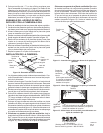
3. Attach supplemental brackets using 1/2" or 3/4" screws
provided in bracket hardware kit. Use 3 brackets to attach
top to mantel assembly - one at back of each leg assembly
and one at center of header (see Figure 8).
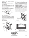
4. Place mantel base next to wall at installation location. See
replaceowner'smanualforinstallationclearances.
5. Place mantel assembly onto mantel base and center left
torightwiththebackushwiththebackofthebase(see
Figure9).
6. Use 1
1
/
4
" screws in pocket holes to attach mantel assem-
bly to mantel base. Using brackets and 1/2" - 3/4" screws
from bracket hardware kit, attach support brackets to base
and mantel assembly - one at each back corner of the leg
sidesandoneoneachlegfront(seeFigure9).
Figure 9 - Attaching Mantel Assembly to Mantel Base
1
1
/
4
"
Screws
Mantel Base
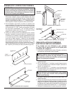
Figure 6 - Mantel Kit Installation for Dimplex
1
1
/
4
" Screw
Short Wood
Block
Dimplex
Kit Header
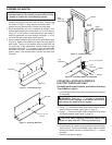
Figure 5 - Attaching Blocks to Dimplex Header
Mantel
Header
1
1
/
4
"
Screw
Short Wood
Block
Dimplex
Header
Long Wood
Block
Long Wood
Block
Bracket
1/2" or 3/4"
Screw
1/2" or 3/4"
Screw
Bracket