


www.desatech.com
113093-01H 15
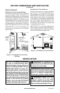
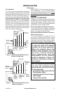
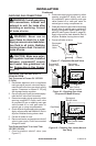
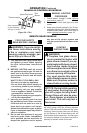
Figure 15 - Gas Connection (Variable
Manually-Controlled Models Only)
Tee Pipe Cap
Joint Nipple
3" Minimum
From External
Regulator (11" W.C.**
to 14" W.C. Pressure)
NATURAL
From Gas Meter
(5" W.C.** to
10.5" W.C.
Pressure)
CSA Design-Certied
Equipment Shutoff Valve
With 1/8" NPT Tap*
Approved Flexible
Gas Hose (if allowed
by local codes)
Sediment Trap
Gas
Regulator
INSTALLATION
Continued
Installation must include an equipment shutoff
valve, union and plugged 1/8" NPT tap. Locate
NPT tap within reach for test gauge hook up.
NPT tap must be upstream from heater (see
Figure 15 or 16, depending on your model).
IMPORTANT: Install equipment shutoff valve
in an accessible location. The equipment
shutoff valve is for turning on or shutting off
the gas to the appliance.
Check your building codes for any special
requirements for locating equipment shutoff
valve to replaces.
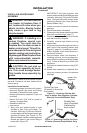
Apply pipe joint sealant lightly to male NPT
threads. This will prevent excess sealant from
going into pipe. Excess sealant in pipe could
result in clogged heater valves.
We recommend that you install a sediment trap
in supply line as shown in Figure 15 or Figure
16, page 15, depending on your model. Lo-
cate sediment trap where it is within reach
for cleaning. Install in piping system between
fuel supply and heater. Locate sediment
trap where trapped matter is not likely to
freeze. A sediment trap traps moisture and
contaminants. This keeps them from going
into heater controls. If sediment trap is not
installed or is installed wrong, heater may
not run properly.
* Purchase the optional CSA design-certied
equipment shutoff valve from your dealer.
** Minimum inlet pressure for purpose of input
adjustment.
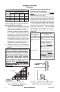
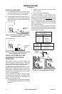
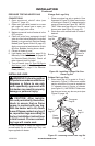
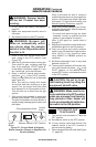
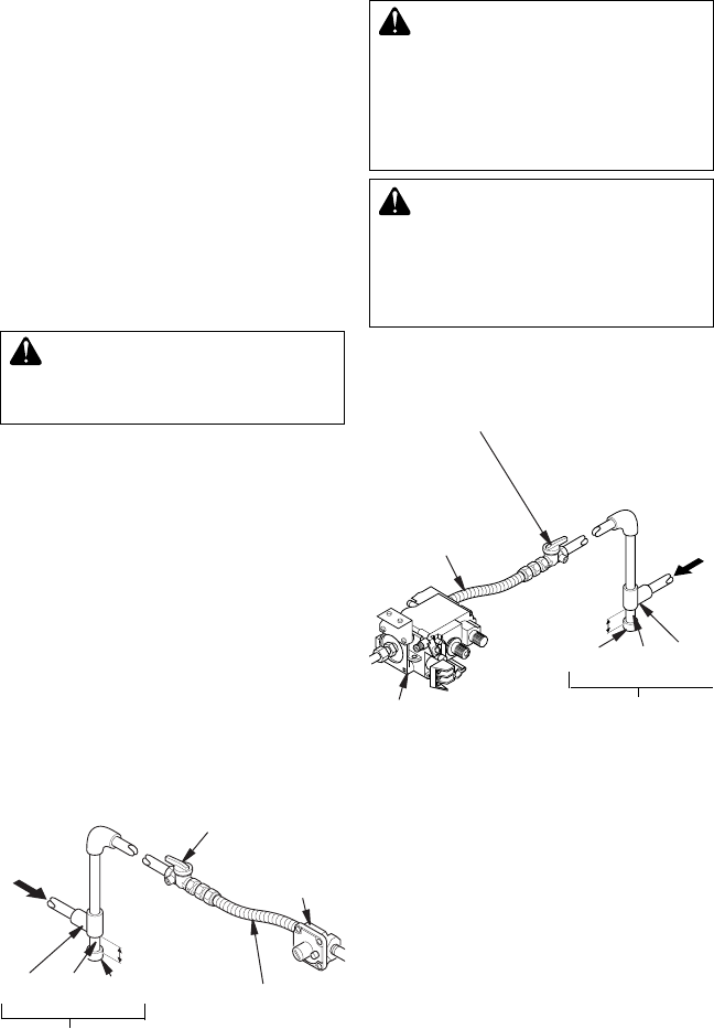
Figure 16 - Gas Connection (Remote-
Ready Models Only)
Gas
Control
3” Minimum
CSA Design-
Certied Equipment
Shutoff Valve With
1/8" NPT Tap*
Approved
Flexible
Gas Hose (if
allowed by
local codes)
From External
Regulator (11"
W.C.** to 14" W.C.
Pressure)
NATURAL
From Gas Meter
(5" W.C.** to
10.5" W.C.
Pressure)
Cap Pipe Tee
Nipple Joint
Sediment Trap