


110398-01A
For more information, visit www.desatech.com
For more information, visit www.desatech.com
11
11
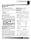
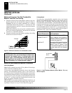
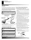
4. Place logs in their proper position on heater base. See Install-
ing Logs, page 13.
5. Center heater base and logs front-to-back and side-to-side in
fireplace.
6. Carefully remove logs without moving heater base.
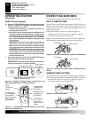
7. Mark screw locations through one hole on each side of the
mounting bracket (see Figure 12). If installing in a brick-bot-
tom fireplace, mark screw locations in mortar joint of bricks.
8. Remove heater base from fireplace. If installing optional con-
trol accessories, do so at this time. Follow all directions pro-
vided with accessory.
9. Drill holes at marked locations using 3/16" drill bit.
10. Attach base assembly to fireplace floor using two masonry
screws (in hardware package).
INSTALLATION
Continued
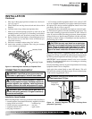
O
F
F
P
I
L
O
T
O
N
H
I
L
O
Figure 12 - Attaching Base Assembly to Fireplace Floor
Masonry Screw
Mounting Flanges
CONNECTING TO GAS SUPPLY
WARNING: A qualified service person must con-
nect heater to gas supply. Follow all local codes.
WARNING: Never connect propane/LP heater di-
rectly to the propane/LP supply. This heater requires an
external regulator (not supplied). Install the external
regulator between the heater and propane/LP supply.
Installation Items Needed
Before installing heater, make sure you have the items listed below.
• external regulator (for propane/LP units only, supplied by installer)
• piping (check local codes) • sediment trap
• sealant (resistant to propane/LP gas) • tee joint
• equipment shutoff valve * • pipe wrench
• test gauge connection *
WARNING: Never connect natural gas heater to
private (non-utility) gas wells. This gas is commonly
known as wellhead gas.
INSTALLATION
Installing Heater Base Assembly (Cont.)
Connecting To Gas Supply
* A CSA design-certified equipment shutoff valve with 1/8" NPT
tap is an acceptable alternative to test gauge connection. Purchase
the optional CSA design-certified equipment shutoff valve from
your dealer. See Accessories, page 24.
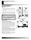
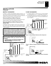
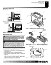
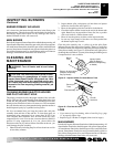
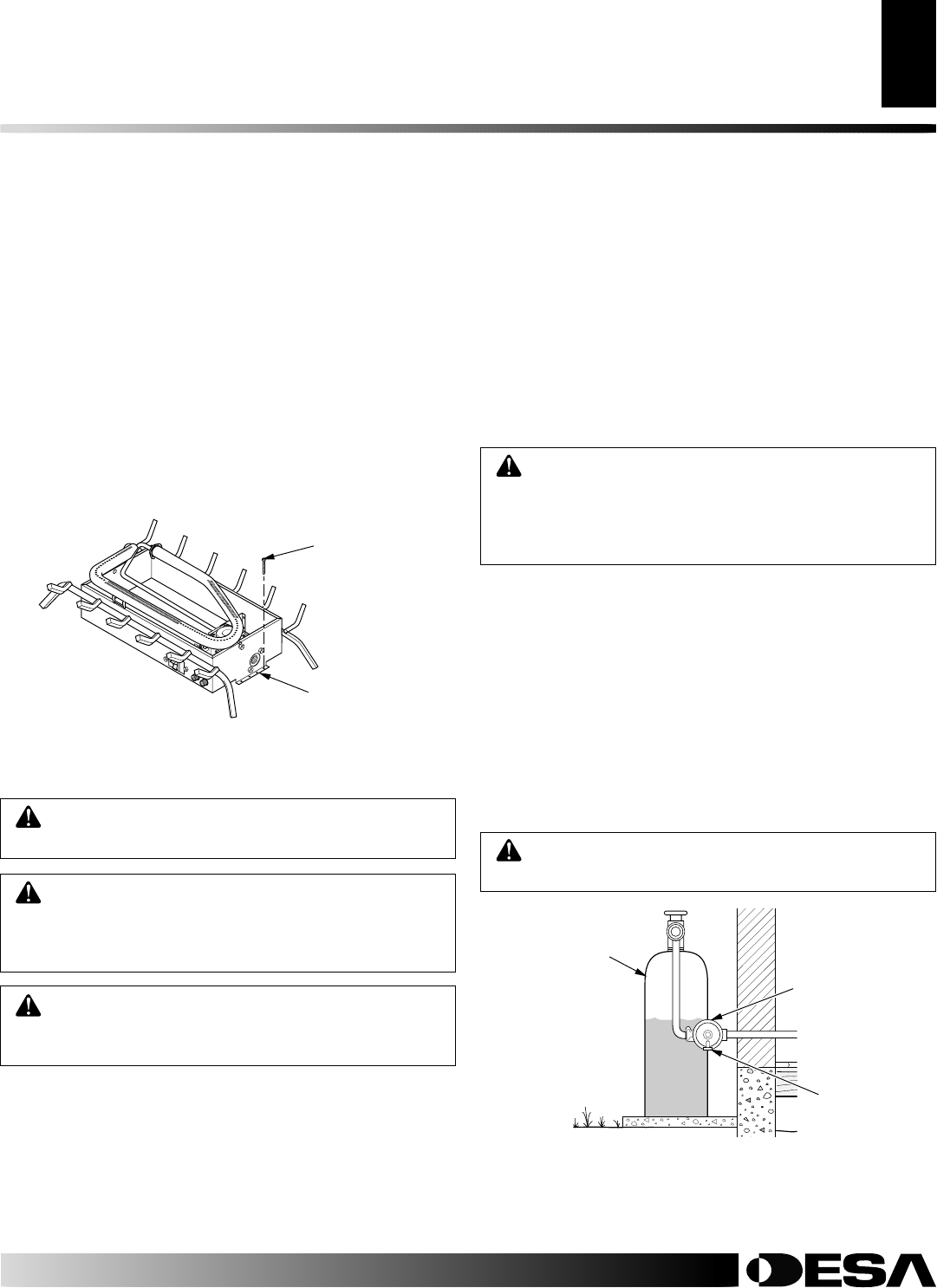
For propane/LP units, the installer must supply an external regula-
tor. The external regulator will reduce incoming gas pressure. You
must reduce incoming gas pressure to between 11 and 14 inches of
water. If you do not reduce incoming gas pressure, heater regulator
damage could occur. Install external regulator with the vent point-
ing down as shown in Figure 13. Pointing the vent down protects it
from freezing rain or sleet.
Installation must include an equipment shutoff valve, union, and
plugged 1/8" NPT tap. Locate NPT tap within reach for test gauge hook
up. NPT tap must be upstream from heater (see Figure 14, page 12).
IMPORTANT:
Install equipment shutoff valve in an accessible
location. The equipment shutoff valve is for turning on or shutting
off the gas to the appliance.
Check your building codes for any special requirements for locating
equipment shutoff valve to fireplaces.
Apply pipe joint sealant lightly to male NPT threads. This will
prevent excess sealant from going into pipe. Excess sealant in pipe
could result in clogged heater valves.
CAUTION: Use only new, black iron or steel pipe.
Internally-tinned copper tubing may be used in certain
areas. Check your local codes. Use pipe of 1/2" diam-
eter or greater to allow proper gas volume to heater. If
pipe is too small, undue loss of volume will occur.
WARNING: Use pipe joint sealant that is resistant
to liquid petroleum (LP) gas.
Figure 13 - External Regulator With Vent Pointing Down
(propane/LP gas only)
Propane/LP
Supply Tank
External
Regulator
Vent
Pointing
Down