


9
901272
OWNER’S MANUAL
INSTALLATION
Continued
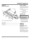
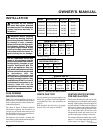
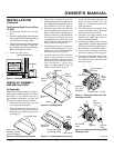
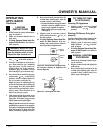
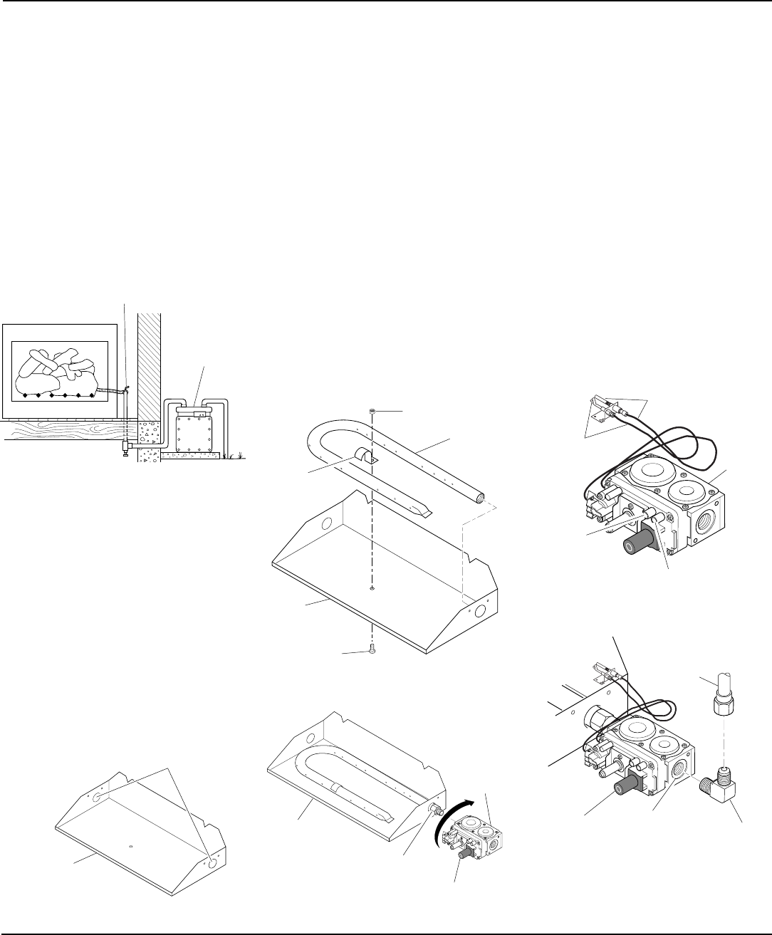
Figure 7 - Checking Gas Joints
HEARTH KIT ASSEMBLY
AND INSTALLATION
Kit Assembly
Note:
The following instructions apply to
both standard single bar burners, as well as
dual flame “U” style burners. Be sure all
pipe threaded connections are tight, and
have thread compound to prevent leaks.
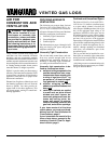
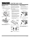
1. Determine which side the gas line will
be coming into the fireplace.
2. Using a hammer and screw driver, re-
move knock-out plug from the side of
the pan that corresponds to the gas line
(see Figure 8).
Continued
Test Pressures Equal To or Less Than
1/2 PSIG
1. Close manual shutoff valve (see Fig-
ure 7).
2. Pressurize supply piping system by either
using compressed air or opening main gas
valve located on or near gas meter.
3. Check all joints from gas meter to manual
shutoff valve (see Figure 7). Apply mix-
ture of liquid soap and water to gas joints.
Bubbles forming show a leak.
4. Correct all leaks at once.
Gas Meter
Manual Shutoff Valve
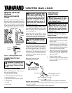
Figure 8 - Knock-Out Plug Locations
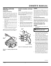
Figure 9 - Installing Burner
Knock-Out Plugs
Nut
Burner
Clamp
Burner
Pan
Screw
Burner
Manifold
3. Place burner manifold in pan with
threaded opening facing open knock-out
plug.
Note:
If using propane/LP gas, see
Propane/LP Gas Conversion, page 10.
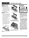
4. Thread the gas control valve onto the
burner inlet fitting (see Figure 10). Use
thread sealant on the male threads of
the burner inlet fitting. Hold the burner
inlet fitting with a wrench to prevent
overtightening the connection to the
burner. Make sure the control knob is
facing the front (see Figure 10).
5. Using burner clamp, screw, and nut pro-
vided, assemble clamp to pan (“U” style
burners only). This will hold the burner
manifold in place (see Figure 9).
6. Attach the pilot gas line to the pilot
outlet of the gas control valve and
tighten. Connect the thermocouple to
the terminal block on the gas control
valve. See Figure 11. Do not over-
tighten. If using propane/LP gas, see
Changing Pilot Orifice, page 11.
Burner Pan
Assembly (Facing
Front of Fireplace)
Figure 10 - Installing Gas Control Valve
7. Install the inlet fitting into the inlet
opening of the gas control valve (see
Figure 12). Use thread sealant on the
male pipe threads.
8. Place the burner pan assembly in the
center of the fireplace floor. Make sure
the front of pan faces forward.
9. Thread the gas supply adaptor to the
fireplace gas supply pipe. Adjust to
most convenient position.
10. Install the gas connector tube to the gas
supply adaptor. Carefully shape tube and
attach to gas inlet fitting (see Figure 12).
Be careful not to cause kinks in tube.
11. Test for leaks following instructions
under Testing Burner for Leaks, page 11.
12.
Retighten and adjust the location of the
gas control as necessary. The gas con-
trol should be level, with the control
knob to the front.
O
F
F
P
I
L
O
T
O
N
Burner Inlet Fitting
(containing orifice)
Gas
Control
Valve
Burner Pan
Assembly
Control Knob
O
F
F
P
I
L
O
T
O
N
Figure 11 - Gas Control Valve with Ther-
mocouple and Pilot
Thermocouple
and Line
Pilot and Line
Gas
Control
Valve
Pressure
Tap - Out
(Manifold)
Pressure Tap - In (Inlet)
Figure 12 - Installing Inlet Fitting and Gas
Connector Tube
O
F
F
P
I
L
O
T
O
N
Gas Control
Valve
Gas Inlet
Fitting
Gas
Connector
Tube
Inlet
Opening