


108861-01D
For more information, visit www.desatech.com
For more information, visit www.desatech.com
28
OPERATING FIREPLACE
Operating Optional GWMT1 Wall Mounted Thermostat
Operating Optional Blower Accessory
INSPECTING BURNERS
Pilot Assembly
Burner Flame Pattern
OPERATING FIREPLACE
Continued
OPERATING OPTIONAL
BLOWER ACCESSORY
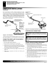
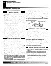
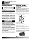
Locate the blower controls by opening the lower louver panel on
the fireplace. Blower controls are located on the left side of the
switch bracket to the left just inside the louver panel.
The BK manual blower and the BKT thermostatically-con-
trolled blower have an ON setting and an OFF setting. The
blower will only run when the switch is in the ON position. In the
OFF position, the blower will not operate.
Note for BKT Only:
If you are using BKT blower with optional
thermostat (wall mounted or remote control) for the fireplace,
your fireplace and blower will not turn on and off at the same
time. The fireplace may run for several minutes before the
blower turns on. After the heater modulates to the pilot position,
the blower will continue to run. The blower will shut off after the
firebox temperature decreases.
The blower helps distribute heated air from the fireplace.
Periodically check the louvers of the firebox and remove any
dust, dirt, or other obstructions that will hinder the flow of air.
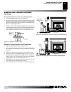
OPERATING OPTIONAL GWMT1
WALL MOUNTED THERMOSTAT
Light the fireplace as instructed in Lighting Instructions on
page 26. Set wall thermostat to desired temperature.
This thermostat has been electronically calibrated at the factory
and requires no adjustment or leveling.
Upon installation, the thermostat must be allowed to stabilize at
room temperature for a minimum of 30 minutes for proper
operation.
To turn the fireplace off, adjust thermostat to the lowest setting
and turn the gas control knob back to PILOT. The pilot will
remain lit.
IMPORTANT:
To turn the pilot off, turn the gas control knob
on the heater to the OFF position.
WARNING: Do not connect the thermostat to a
power source. Electrical shock and/or a fire hazard
will occur.
Check pilot flame pattern and burner flame patterns often.
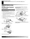
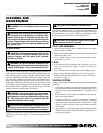
PILOT ASSEMBLY
The pilot assembly is factory preset for the proper flame height.
Alterations may have occurred during shipping and handling. Call
a qualified service person to readjust the pilot if necessary.
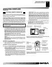
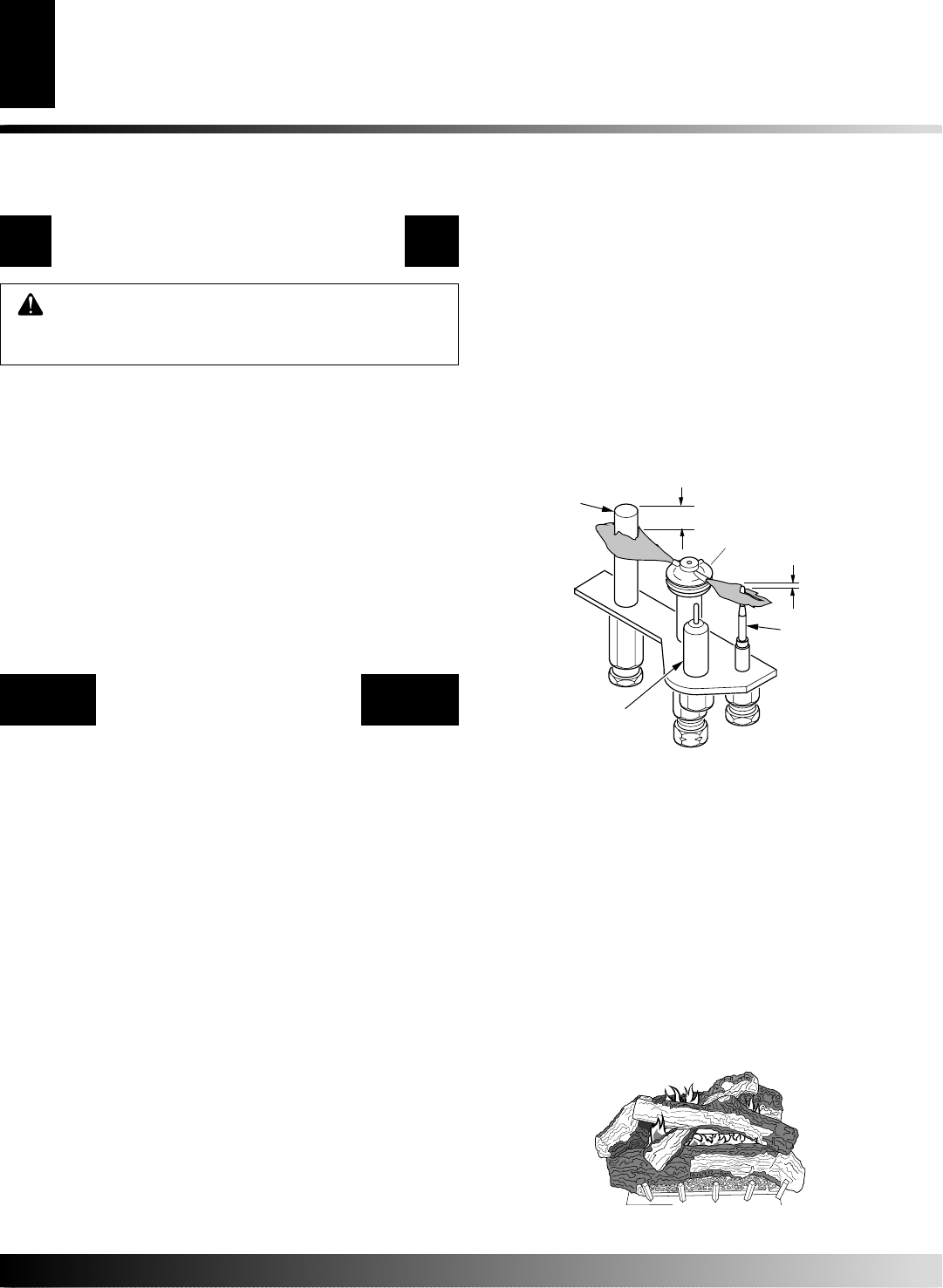
The height of the thermopile must be 3/8" to 1/2" above the pilot
flame as shown in Figure 55. The thermocouple must be at a height
of about 1/8" above the pilot flame. The flame from the pilot burner
must extend beyond both the thermocouple and thermopile.
If you pilot assembly does not meet these requirements:
• turn fireplace off (see To Turn Off Gas to Appliance, page 26)
• see Troubleshooting, pages 30 through 32
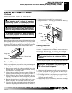
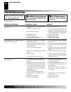
INSPECTING BURNERS
BURNER FLAME PATTERN
Burner flames will be steady; not lifting or floating. Flame patterns
will be different from unit to unit and will vary depending on
installation type and weather conditions.
If the vent configuration is installed incorrectly, the flames will lift
or "ghost". This can be dangerous. Inspect the flames after installa-
tion to ensure proper installation and performance.
Figure 56 shows a typical flame pattern for (V)V36 and (V)V42
series models.
If burner flame pattern differs from that described:
• turn fireplace off (see To Turn Off Gas to Appliance, page 26)
• see Troubleshooting, pages 30 through 32
Figure 56 - Typical Flame Pattern for (V)V36 and (V)V42 Series
Models
Thermocouple
Thermopile
1/8"
Pilot Burner
Piezo
Ignitor
Figure 55 - Pilot Assembly
3/8" to 1/2"