


108117
For more information, visit www.desatech.com
For more information, visit www.desatech.com
12
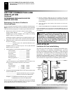
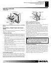
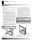
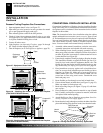
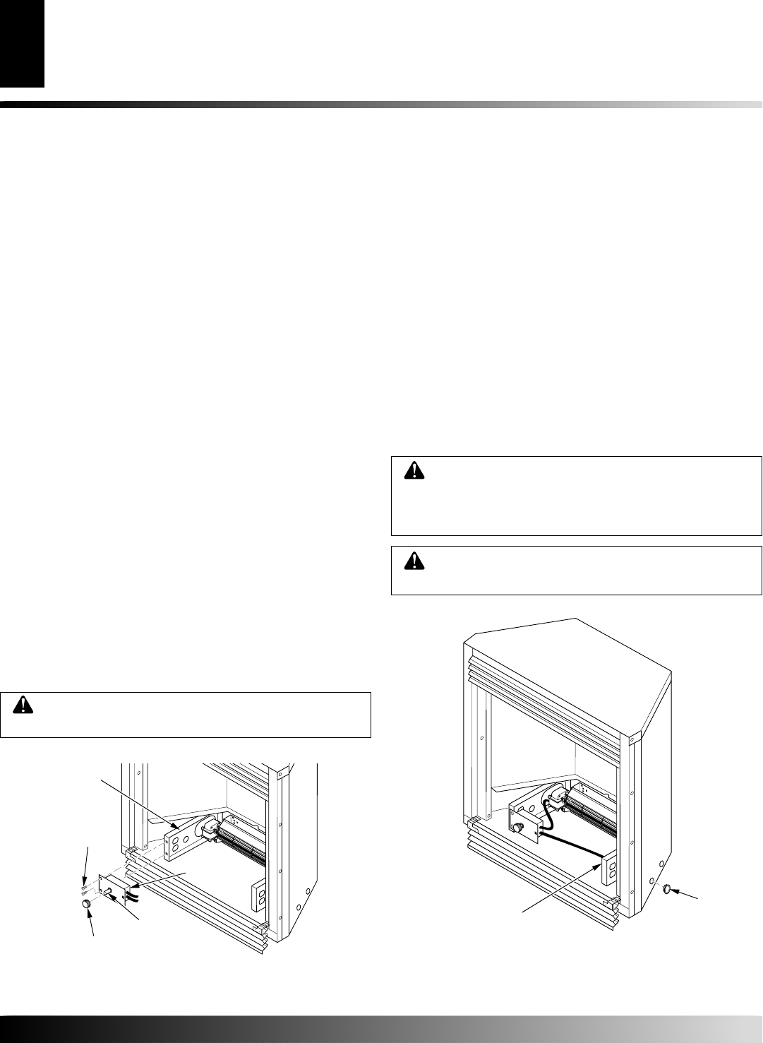
Figure 15 - Attaching Speed Control to Firebox (VTGF33NR/
VTGF33PR Shown)
Screws
Speed
Control
Control Knob
Left Floor
Support
Bracket
Control
Shaft
5. Be certain that all wire terminals are securely attached to ter-
minals on blower motor and that the screw retaining the green
ground wire is tight.
6. Place control knob provided on plastic control shaft of speed
control.
7. Mount the speed control on the front leg of the left floor sup-
port bracket using 2 screws provided (see Figure 15).
8. Plug in blower power cord.
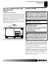
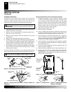
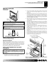
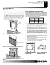
a. If your fireplace system is installed as a freestanding unit
with an accessory mantel, determine whether the power
cord will exit the left side or the right side of the firebox.
Install 1 plastic bushing provided into the 1.5" hole in the
floor support bracket on the exit side (see Figure 16). Install
the second plastic bushing provided into the 1.5" hole in the
outer casing through which the power cord will exit. Route
power cord through both plastic bushings and plug the power
cord into a properly grounded 3-prong wall receptacle near
the firebox.
b.If your fireplace system installation is recessed and if an
outlet is not installed in your fireplace, you must install
the GA3555 Outlet kit with cover in your fireplace which
will supply a convenient 3-prong grounded electrical outlet
for your blower. Refer to the installation manual provided
with the model GA3555 accessory for instructions on wir-
ing the duplex outlet.
Note:
A qualified installer must make all electrical connections.
9. Check to make sure that all electrical cords are completely
clear of the blower wheel and that there are no other foreign
objects in blower wheel. Turn blower on and check for opera-
tion. Turn blower off by rotating knob fully counterclockwise
before continuing.
INSTALLATION
Installing Variable Speed Blower Accessory (Cont.)
INSTALLATION
Continued
CAUTION: Never touch the blower wheel while in
operation.
WARNING: Failure to position the parts in accor-
dance with supplied diagrams or failure to use only
parts specifically approved with this heater may re-
sult in damage or personal injury.
WARNING: A qualified service person must con-
nect fireplace to gas supply. Follow all local codes.
Plastic
Bushing
Right Floor
Support Bracket
Figure 16 - Installing Plastic Bushing for Power Cord (VTGF33NR/
VTGF33PR Shown)
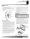
10. Peel off backing paper and stick supplied wiring diagram de-
cal near center of firebox bottom (Figure 17, page 13).
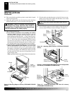
11. If gas connections have been made and checked, replace fire-
place floor assembly. Feed flexible gas supply line into fire-
place base area while replacing fireplace floor assembly. Make
sure the entire flexible gas line is in fireplace base area.
IMPORTANT:
Do not pick up fireplace floor assembly by
burners. This could damage burners. Only handle base by
grates.
Note:
Be careful of all wires and components on un-
derside of floor assembly.
12. Reattach fireplace floor assembly with screws removed in step
3 of Removing Fireplace Screen and Floor Assembly, page 8.
Note:
Discard the remaining hardware items. After assembly,
make sure all wires are completely clear of blower wheel.
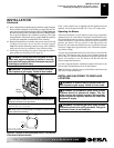
13. Install logs (see Installing Logs, pages 21 through 23) and fire-
place screen (see Installing Screen, page 24).