


www.desatech.com
114370-01D6
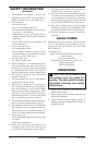
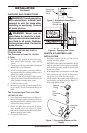
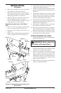
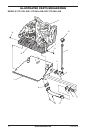
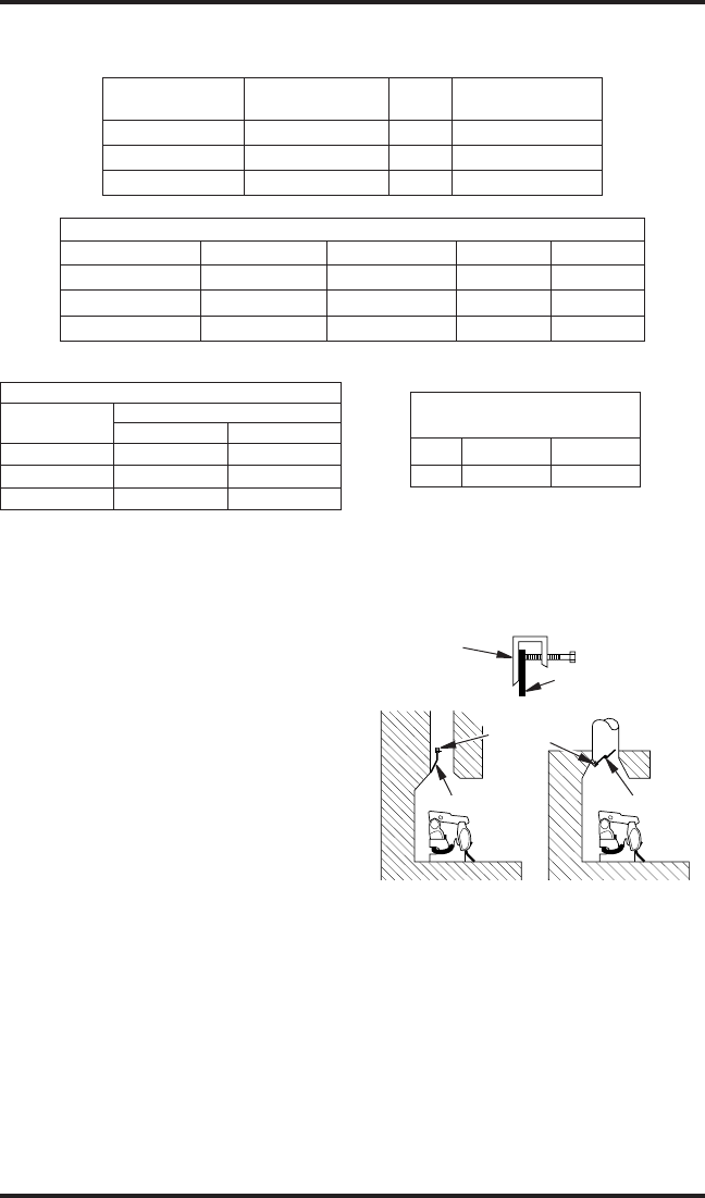
Figure 3 - Attaching Damper Clamp
Manufactured
Fireplace
Masonry
Fireplace
Damper
Damper
Clamp
Damper
Damper
Clamp
Damper
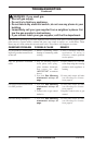
VENTING SPECIFICATIONS FOR
INSTALLATION
The replace chimney ue and vent must be draft-
ing properly. To check the vent for proper drafting:
Light a tightly rolled newspaper on one end and
place it at the inside front edge of the replace.
Observe the smoke and be sure the vent is properly
drawing it up the chimney. If the smoke spills out
into the room, extinguish the ame and remove any
obstruction until proper venting is achieved.
The chimney ue must remain open a minimum of 3"
at all times during the operation of this log set.
INSTALLING DAMPER CLAMP
Secure the damper stop clamp to the edge of the
damper as shown in Figure 3. If for any reason this
clamp doesn't work on your replace, another suit-
able clamp or permanent stop must be installed, or
the damper blade must be cut or removed.
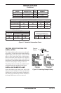
MODEL
BURNER
DESCRIPTION
BTU
INPUT
MINIMUM VENT
OPENING
VTD-18N-JHB 18" Ramp 59,000 8" dia.
VTD-24N-JHB 24" Ramp 69,000 8" dia.
VTD-30N-JHB 30" Ramp 74,000 8" dia.
INSTALLATION
Continued
MINIMUM FIREBOX SIZES
MODEL FRONT WIDTH BACK WIDTH* DEPTH HEIGHT
VTD-18N-JHB 28" 16" 14" 18"
VTD-24N-JHB 29
3
/
4
" 17" 15
1
/
2
" 18"
VTD-30N-JHB 36" 27" 18" 18"
*At depth indicated
BURNER ORIFICE
LOG SIZE
NATURAL
INCHES NUMBER
18" 0.1495 25
24" 0.1570 22
30" 0.1660 19
FUEL INLET PRESSURE
SPECIFICATIONS (W.C.)
MIN. MAX.
NG 5.5" 10.5"
Figure 2 - Technical Information Charts