


www.desatech.com
108661-01F
14
VENTING INSTALLATION
INSTRUCTIONS
Continued
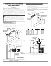
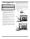
HIGH ALTITUDE INSTALLATION
Your DESA direct-vent replace has been CSA tested and approved
for elevations from 0-2000 feet (USA) and elevations from 0-4500
feet (Canada).
When installing this replace at an elevation above 2000 feet (in the
USA), you may need to decrease the input rating by changing the
existing burner orice to a smaller size. Reduce input 4% for each
1000 feet above sea level. Check with your local gas company for
proper orice size identication.
When installing this replace at an elevation above 4500 feet (in
Canada), check with local authorities.
Consult your local gas company to help determine the proper orice
for your location.
For assistance with any high altitude installation contact DESA
Customer Service Department at 1-866-672-6040.
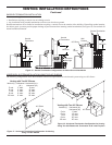
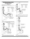
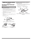
PARTS LISTS FOR VENTING KITS AND
DESA Pipe & Vent Kits
Number Description
P47-6 6" Section Coaxial Pipe - Galvanized
P47-12 12" Section Coaxial Pipe - Galvanized
P47-24 24" Section Coaxial Pipe - Galvanized
P47-36 36" Section Coaxial Pipe - Galvanized
P47-48 48" Section Coaxial Pipe - Galvanized
PA47-712 Adjustable 7"-12" Section Coaxial Pipe - Galvanized
VKG-47 Ground Floor Vent Kit - Galvanized
Includes: 45° Elbow, 7"-12" Adjustable Pipe, Wall Fire-
stop, Horizontal Square Termination, and 16 Screws
VKB-47 Basement Vent Kit - Galvanized
Includes: 45° Elbow, 7"-12" Adjustable Pipe, Wall
Firestop, Horizontal Square Termination, 4' Pipe, 90°
Elbow, and 20 Screws
VKS-47 Snorkel Kit - Galvanized
Includes: 45° Elbow, 7"-12" Adjustable Pipe, Wall Fire-
stop, 36" Snorkel Termination, 4' Pipe, 90° Elbow, and
26 Screws
VKR-47 Roof Vent Kit - Galvanized
Includes: 45° Elbow, 7"-12" Adjustable Pipe, Flue
Restrictor, Vertical High Wind Termination, 2' Pipe, 4'
Pipe, Firestop Plate, Roof Flashing (0/12-6/12), and
26 Screws
VKC-47 Corner Vent Kit - Galvanized
Includes: 45° Elbow, 7"-12" Adjustable Pipe, Horizon-
tal Termination, 6" Pipe, 90° Elbow, Wall Firestop, and
18 Screws
HTK Horizontal Round Termination Kit
Includes: Round Termination, Wall Firestop, and 45°
Elbow
DESA Elbows
Number Description
E47-45 45° Elbow - Galvanized
E47-90 90° Elbow - Galvanized
DESA Terminations
Number Description
HT-47 Horizontal Round Termination - Galvanized
HTS-47 Horizontal Square Termination - Galvanized
VT-47 Vertical Round Termination - Galvanized
ST-47-14 14" Snorkel Termination - Galvanized
ST-47-36 36" Snorkel Termination - Galvanized
DESA Venting Accessories
Number Description
SC-47 Storm Collar - Galvanized
WF-47 Wall Firestop - Galvanized
RF-47-6 Roof Flashing - 0 to 6/12 Pitch - Galvanized
RF-47-12 Roof Flashing - 6/12 to 12/12 Pitch - Galvanized
VR-47 Vertical Restrictor - Galvanized
S-47 Combustible Siding Standoff - Galvanized
WS-47 Wall Strap
FP-47 Firestop Plate
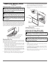
FIREPLACE INSTALLATION
Use proper gas type for the replace unit you are installing. If you
have conicting gas types, do not install replace. See retailer
where you purchased the replace for proper replace according
to your gas type.
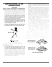
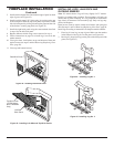
INSTALLING OPTIONAL BLOWER
gas connections, shut off gas supply and disconnect
person to do this.
WARNING: If there is a duplex electrical outlet in-
base area, be sure that the electrical power to the outlet
is turned off before proceeding with blower installation.
Failure to do this may result in serious injury.
Model BK Installation
Follow all instructions provided in the blower accessory kit.
1. Attach the power cord to the blower motor by rmly pushing
the two female terminals at the end of the power cord onto the two
spade terminals on the blower motor (see Figure 25, page 15).
2. Attach green ground wire from power cord to blower housing
using screw provided (see Figure 25, page 15). Tighten screws
securely.