


www.desatech.com
107886-01J16
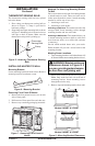
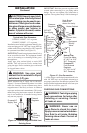
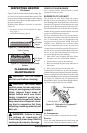
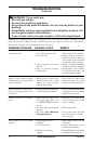
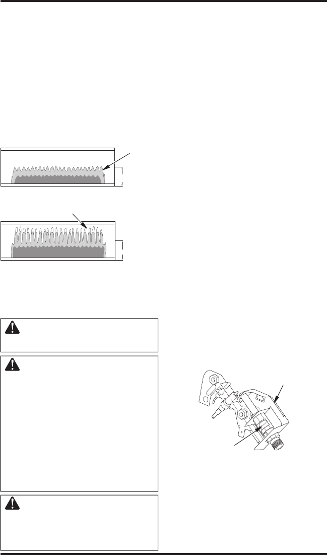
Figure 23 - Correct Burner Flame Pattern
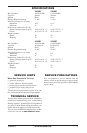
Yellow Tipping
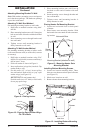
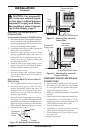
Figure 24 - Incorrect Burner Flame
Pattern
1/2 Glass
Height
Blue
Flame
1/2 Glass
Height
CLEANING AND
MAINTENANCE
WARNING: Turn off heater
and let cool before cleaning.
CAUTION: You must keep
control areas, burner and circu-
lating air passageways of heater
clean. Inspect these areas of
heater before each use. Have
heater inspected yearly by a
qualified service person. Heater
may need more frequent clean-
ing due to excessive lint from
carpeting, bedding material, pet
hair, etc.
WARNING: Failure to keep
the primary air opening(s) of
the burner(s) clean may result in
sooting and property damage.
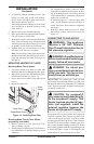
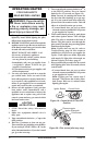
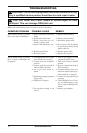
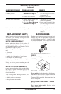
Figure 25 - Pilot Inlet Air (Propane/LP
Pilot Shown)
Pilot Assembly
Pilot Air Inlet
ODS/PILOT AND BURNER
Use a vacuum cleaner, pressurized air or small,
soft bristled brush to clean.
BURNER PILOT AIR INLET
The primary air inlet holes allow the proper
amount of air to mix with the gas. This provides a
clean burning flame. Keep these holes clear of dust,
dirt and lint. Clean these air inlet holes prior to each
heating season. Blocked air holes will create soot.
We recommend that you clean the unit every three
months during operation and have heater inspected
yearly by a qualified service person.
We also recommend that you keep the burner
tube and pilot assembly clean and free of dust and
dirt. To clean these parts we recommend using
compressed air no greater than 30 PSI. Your local
computer store, hardware store or home center
may carry compressed air in a can. You can use a
vacuum cleaner in the blow position. If using com
-
pressed air in a can, please follow the directions on
the can. If you donʼt follow directions on the can,
you could damage the pilot assembly.
1. Shut off the unit, including the pilot. Allow
the unit to cool for at least thirty minutes.
2. Inspect burner, pilot for dust and dirt.
3. Blow air through the ports/slots and holes in
the burner.
4. Never insert objects into the pilot tube.
Clean the pilot assembly also. A yellow tip on the pi
-
lot flame indicates dust and dirt in the pilot assembly.
There is a small pilot air inlet about two inches from
where the pilot flame comes out of the pilot assembly
(see Figure 25). With the unit off, lightly blow air
through the air inlet. You may blow through a drink-
ing straw if compressed air is not available.
INSPECTING HEATER
Continued
CABINET
Air Passageways
Use a vacuum cleaner or pressurized air to clean.
Exterior
Use a soft cloth dampened with a mild soap and
water mixture. Wipe the cabinet to remove dust.
Figure 23 shows a correct burner flame pattern. Fig
-
ure 24 shows an incorrect burner flame pattern. The
incorrect burner flame pattern shows yellow tipping
of the flame. It also shows the flame higher than 1/2
the glass panel height.
If burner flame pattern is incorrect, as shown in
Figure 24
• turn heater off (see To Turn Off Gas To Appli
-
ance, page 15
• see Troubleshooting, page 18