


www.desatech.com
107886-01J 15
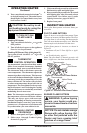
BURNER FLAME PATTERN
WARNING: If yellow tipping
occurs, your heater could pro-
duce increased levels of carbon
monoxide.
NOTICE: Do not mistake orange
flames with yellow tipping. Dirt
or other fine particles enter the
heater and burn causing brief
patches of orange flame.
OPERATING HEATER
Continued
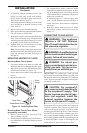
8. Turn control knob counterclockwise
to desired heating level. The main burner
should light. Set control knob to any heat
level between 1 and 5.
CAUTION: Do not try to ad-
just heating levels by using the
equipment shutoff valve.
TO TURN OFF GAS
TO APPLIANCE
Shutting Off Heater
1. Turn control knob clockwise
to the
OFF position.
2. Turn off all electric power to the appliance
if service is to be performed.
Shutting Off Burner Only (pilot stays lit)
Turn control knob clockwise
to the
PILOT position.
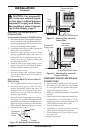
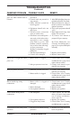
THERMOSTAT
CONTROL OPERATION
The thermostatic control used on these models
differs from standard thermostats. Standard
thermostats simply turn on and off the burner.
The thermostat used on this heater senses the
room temperature. The thermostat adjusts the
amount of gas flow to the burner. This increases
or decreases the burner flame height. At times the
room may exceed the set temperature. If so, the
burner will shut off. The burner will cycle back
on when room temperature drops below the set
temperature. The control knob can be set to any
heat level between 1 and 5. Selecting the 5 setting
will cause the burner to remain fully on without
modulating down in most cases.
Note: The thermostat sensing bulb measures
the temperature of air near the heater cabinet.
This may not always agree with room tem
-
perature (depending on housing construction,
installation location, room size, open air tem
-
peratures, etc.). Frequent use of your heater will
let you determine your own comfort levels.
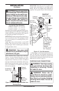
MANUAL LIGHTING
PROCEDURE
1. Remove front panel (see Figure 7, page 9).
2. Follow steps 1 through 5 under Lighting
Instructions, page 14.
3. With control knob pressed in, strike match.
Hold match to pilot until pilot lights.
4. Keep control knob pressed in for 30 seconds
after lighting pilot. After 30 seconds, release
control knob. Now follow step 8, under
Lighting Instructions, pages 14 and 15.
5. Replace front panel.
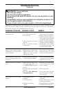
INSPECTING HEATER
Check pilot flame pattern and burner flame pat-
tern often.
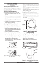
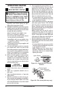
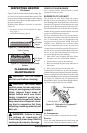
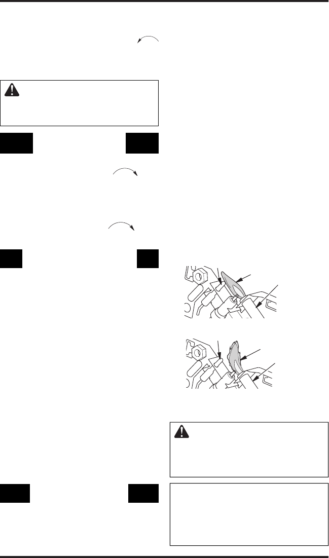
PILOT FLAME PATTERN
Figure 21 shows a correct pilot flame pattern. Figure
22 shows an incorrect pilot flame pattern. The incor
-
rect pilot flame is not touching the thermocouple.
This will cause the thermocouple to cool. When the
thermocouple cools, the heater will shut down.
If pilot flame pattern is incorrect, as shown in
Figure 22
• turn heater off (see To Turn Off Gas to Appli
-
ance)
• see Troubleshooting
, page 18
Note: The pilot flame on natural gas units will
have a slight curve, but flame should be blue and
Figure 22 - Incorrect Pilot Flame Pattern
Figure 21 - Correct Pilot Flame Pattern
Thermocouple
Pilot Burner
Pilot Burner
Thermocouple
Blue Flame
Yellow Flame