


www.desatech.com
108795-01V 9
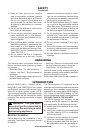
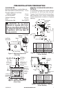
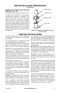
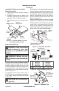
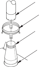
INSTALLING TRANSITION PIPE AND
STARTER COLLAR
The transition pipe and starter collar shown
in Figure 9 are supplied with the replace,
unattached and ready for installation. Re-
move starter collar and set aside. Slide
transition pipe over vent collar and attach
with a minimum of three screws. Replace
starter collar over transition pipe and attach
using four screws located on leg stands (ve
used on model M42). To install B-vent piping,
slide the rst piece of B-vent over transition
pipe and attach with either a minimum of two
screws or other means approved by the vent
manufacturer.
Figure 9 - Installing Transition Pipe and
Starter Collar
B-Vent Piping
Transition Pipe
Starter Collar
Vent Collar
PRE-INSTALLATION PREPARATION
Continued
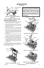
VENTING INSTALLATION
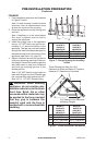
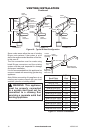
60° or greater. The total vertical height in this
example represents the minimum height of 8
feet and therefore the allowable lateral is 6
feet when the 75% rule applies. If the lateral
length must exceed 75% then the system
must be sized in accordance with Category I
venting tables.
Example2: Shows a multiple offset each at
45° of inclination. Multiple offsets are permit-
ted if they do not exceed 45° of inclination. The
total lengths of the two offsets are not required
to meet the 75% allowable rule.
Example3:Shows a single offset at 45° of
inclination and therefore the lateral length at
10 feet of offset does not have to meet the
75% rule.
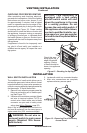
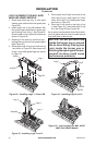
In each case the offsets must be supported
and restops must be positioned wherever
the vent must pass through a sub-oor, ceil-
ing joist or an attic overhang. The vent pipe
must terminate vertically into a listed type vent
cap and extend a sufcient height through
an approved roof ashing, roof jack or a roof
thimble. At all points listed clearances must
be maintained.
Vent terminations must be located in ac-
cordance with height and proximity rules of
NFPA No. 54. These rules apply to vents at
12" diameter or less and require a minimum
height in accordance with the roof pitch and a
minimum of 8 ft. distance from a vertical wall
or obstruction (see Figure 11, page 10).
A B-type venting system must be connected
to the appliance for venting to the outside of
the building.
The following section is provided as a guide
to a standard B-type vent installation.
Standing codes requirements concerning B-
type vent installations may vary within your
state, province or local codes jurisdiction.
Therefore, it is recommended that you check
with your local building codes for specic
requirements or in absence of local codes,
follow Section 7.0 of the current National Fuel
Gas Code ANSI Z223.1/NFPA 54.
This gas appliance must be vented to the
outdoors only and may not be terminated into
an attic space or into a chimney ue servicing
a solid fuel burning appliance.
This appliance may be vented through a
manufactured chimney system or a masonry
chimney using a B-vent adapter or a chim-
ney liner system if all are listed, inspected
and approved by local codes and/or building
authorities.
The examples shown in Figure 10, page 10
are typical of most B-vent installations and
codes practices.
Example1: Shows the minimum allowable
system height and lateral offset for a 60° or
greater inclination. Code species that offsets
at 60° or greater are considered horizontal
and must follow the 75% rule for lateral to
total vertical system height. Codes also allow
only one offset in the total system when at