


www.desatech.com
113195-01B
24
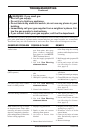
1. Shut off the unit, including the pilot. Allow
the unit to cool for at least thirty minutes.
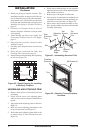
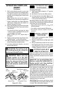
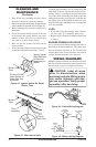
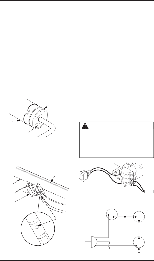
2. Inspect burner, pilot and primary air inlet holes on
injector holder for dust and dirt (see Figure 41).
3. Blow air through the ports/slots and holes in
the burner.
4. Check the injector holder located at the end
of the burner tube again. Remove any large
particles of dust, dirt, lint or pet hair with a
soft cloth or vacuum cleaner nozzle.
5. Blow air into the primary air holes on the
injector holder.
6. In case any large clumps of dust have now been
pushed into the burner repeat steps 3 and 4.
CLEANING AND
MAINTENANCE
Continued
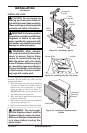
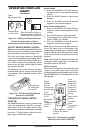
Clean the pilot assembly also. A yellow tip on the
pilot flame indicates dust and dirt in the pilot as
-
sembly. There is a small pilot air inlet hole about
two inches from where the pilot flame comes out
of the pilot assembly (see Figure 42). With the unit
off, lightly blow air through the air inlet hole. You
may blow through a drinking straw if compressed
air is not available.
LOGS
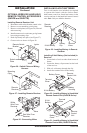
• If you remove logs for cleaning, refer to Install-
ing Logs, page 17, to properly replace logs.
• Replace log(s) if broken or chipped (dime-sized
or larger).
BURNER PRIMARY AIR HOLES
Air is drawn into the burner through the holes in
the fitting at the burner entrance. These holes may
become blocked with dust or lint. Periodically
inspect these holes for any blockage and clean if
needed. Blocked air holes will create soot.
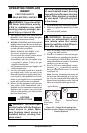
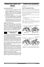
WIRING DIAGRAMS
Note: For proper operation of optional accessories,
the wires from the switch to the control must be con-
nected exactly as shown in Figures 43 and 44.
CAUTION: Label all wires
prior to disconnection when
servicing controls. Wiring errors
can cause improper and dan-
gerous operation. Verify proper
operation after servicing.
Figure 41 - Injector Holder On Outlet
Burner Tube
Burner
Tube
Injector Holder
(May Be Brass
or Aluminum
Depending on
Model)
Primary Air Inlet
Holes (Shape of
Holes May Vary
by Model)
Figure 42 - Pilot Inlet Air Hole
Burner
Tube
Pilot
Assembly
Pilot Air
Inlet Hole
Ports/Slots
A
U
T
O
O
F
F
ON
Thermopile
Figure 43 - Switch Wiring Diagram
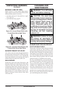
Red
Va
riable
Fan Switch
Fan Switch
(N.O.)
Green
White
On
11
0/115
V.
A.C.
Blower
Motor
Black
Off
1
2
Black
Blue
Figure 44 - Blower Wiring Diagram