


10
105704
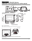
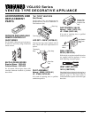
VENTED TYPE DECORATIVE APPLIANCE
VGL450 Series
®
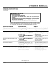
OPERATING
GUIDELINES AND
MAINTENANCE
INSTRUCTIONS
Do not use this appliance if any part has
been under water. Immediately call a quali-
fied service technician to inspect the appli-
ance and to replace any part of the control
system and any gas control which has been
under water.
When lit for the first time, the appliance will
emit a slight odor for about an hour or two.
This is a normal occurrence which is due to
the "curing" of logs and "burn-in" of inter-
nal paints and lubricants used in the manu-
facturing process.
In cleaning, take care not to alter the settings
on the pilot assembly.
WARNING: The logs can be
hot. Handle only when cool.
WARNING: Have a qualified
agency periodically inspect the
vent system at the start of each
heating season so as to be free of
any obstructions which may
hinder normal operation. Never
obstruct the flow of combustion
and ventilation air; keep the front
of the appliance clear of all ob-
stacles and combustible materi-
als such as gasoline or other flam-
mable vapors or liquids. It is also
imperative that the control com-
partments, burners and circulat-
ing air passageways of the appli-
ance be kept clean.
CAUTION: Keep control com-
partment, logs, burners, and area
surrounding the logs clean by
vacuuming or brushing at least
twice a year. Temporary removal
of the log set may ease the clean-
ing of the burner and pilot assem-
bly (see
Installing Logs and Lava
Rock
, pages 8 and 9).
TO TURN OFF GAS
TO APPLIANCE
1. Turn off the wall switch.
2. Turn off all electric power to the ap-
pliance if service is to be performed.
3. Remove control access panel.
4. Turn gas control clockwise
Clockwise
to “OFF”. Do not force.
5. Replace control access panel.
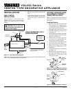
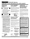
Figure 24 - Pilot
OPTIONAL REMOTE
OPERATION
Note:
The GHRC receiver and hand-
held remote control kit must be purchased
separately (see Accessories & Replacement
Parts, page 14). Follow installation instruc-
tions on pages 6 and 7 of this manual.
1. After lighting, let pilot flame burn for
about one minute. Turn control knob
to ON position. Adjust flame adjust-
ment knob anywhere between HI
and LO. Slide the selector switch to
the REMOTE position.
NOTE:
The
burner may light if hand-held remote
ON button was on when selector
switch was last turned off. You can
now turn the burner on and off with
the hand-held remote control unit.
IMPORTANT:
Do not leave the se-
lector switch in the REMOTE posi-
tion when the pilot is not lit. This will
drain the battery.
IMPORTANT:
Be sure to press the
ON/OFF buttons on the hand-held
remote control unit for up to 3 sec-
onds to assure proper operation.
2. Press the ON/OFF button to turn the
burner on and off. When turning
burner off, the pilot will remain lit.
IMPORTANT:
To turn the pilot off,
manually turn the control knob on
the heater to the OFF position.
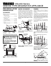
PILOT ASSEMBLY
ADJUSTMENT
The pilot assembly is factory preset for the
proper flame height. Alterations to these
settings may have occurred during shipping
and handling, if this is the case, some minor
readjustments may be necessary.
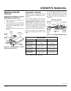
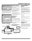
The pilot assembly is located behind the burner
tube on the right hand side. The thermopile
height should be at a distance of 3/8" to 1/2"
from the pilot flame (see Figure 25).
BURNER FLAME
ADJUSTMENT
Figure 25 - Correct Pilot Flame Pattern
The Air Shutter, located at the base of the
Main Burner Tube has been factory preset
to the proper air to gas ratio which results in
a long, blue flame (see Figure 26).
If readjustment is necessary, you can restore
proper flame setting by loosening the air
shutter screw and rotating the air shutter
until proper flame setting is achieved.
Tighten screw back (see Figure 17, page 7,
for air shutter location).
Closing the Air Shutter reduces the air to gas
mix resulting in a longer, yellow flame
which could cause sooting.
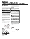
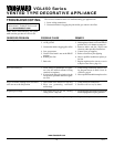
Figure 26 - Burner Flame Patterns
CORRECT
INCORRECT
CLOSE
SHUTTER
INCORRECT
OPEN
SHUTTER
Short, Sharp,
Blowing Flame
Long, Blue Flame
Long, Uneven,
Yellow Flame
OPERATING
FIREPLACE
Continued
3/8" To 1/2"
Thermopile
Pilot
Burner
Thermopile
Pilot Burner