


111640-01B
13
13
For more information, visit www.desatech.com
For more information, visit www.desatech.com
INSTALLATION
Continued
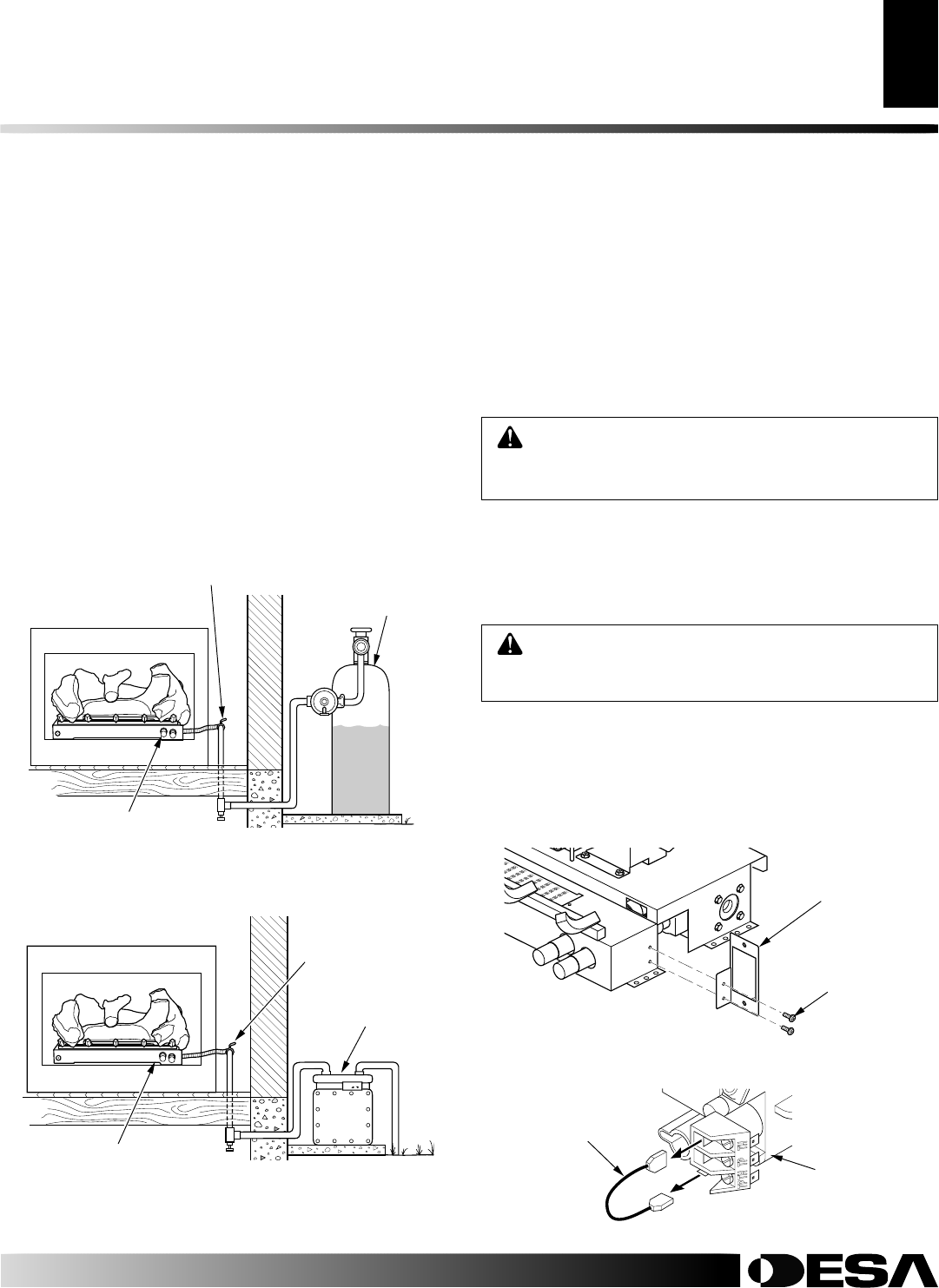
Pressure Testing Heater Gas Connections
1. Open equipment shutoff valve (see Figure 15, page 12).
2. Open propane/LP supply tank valve or main gas valve located
on or near gas meter for natural gas.
3. Make sure control knob of heater is in the OFF position.
4. Check all joints from propane/LP supply tank to equipment
shutoff valve for propane/LP gas (see Figure 16) or from gas
meter to equipment shutoff valve for natural gas (see Figure
17). Apply noncorrosive leak detection fluid to gas joints.
Bubbles forming show a leak.
5. Correct all leaks at once.
6. Light heater (see Operating Heater, pages 15 through 18).
Check all other internal joints for leaks.
7. Turn off heater (see To Turn Off Gas to Appliance, page 16).
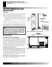
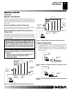
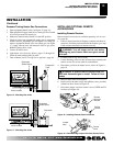
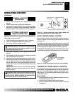
Figure 16 - Checking Gas Joints
Propane/LP
Tank
Equipment
Shutoff Valve
Valve Location
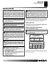
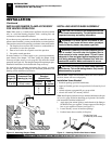
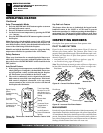
Figure 17 - Checking Gas Joints
Gas Meter
Equipment
Shutoff Valve
Valve Location
INSTALLATION
Checking Gas Connections (Cont.)
Installing Optional Remote Accessories
INSTALLING OPTIONAL REMOTE
ACCESSORIES
Installing Remote Receiver
Remote control accessories are available separately (see Accesso-
ries, page 26).
1. If unit is already installed in fireplace, continue with these in-
structions. If unit has not been installed in fireplace, go to step
6 and continue installation of remote accessory.
2. Carefully remove logs and set aside.
3. Locate mounting screws on sides of heater base assembly and
remove screws. Set screws aside for reinstallation.
4. Disconnect gas line from heater base as shown in Figure 11,
page 10.
WARNING: A qualified service person must con-
nect and disconnect gas to heater. Follow all local
codes.
WARNING: Turn off heater and let cool before
handling any part of heater. Make sure gas is turned
of to unit.
5. Remove heater base from fireplace.
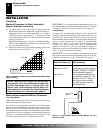
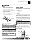
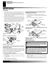
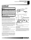
6. Install receiver bracket to base with phillips screws provided
in hardware kit as shown in Figure 18.
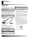
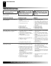
7. Disconnect jumper wire from control valve at TPTH and TH
locations (see Figure 19).
Figure 19 - Disconnecting Jumper Wire from Control Valve
Jumper
Wire
Control
Valve
Figure 18 - Installing Remote Receiver Bracket
Remote
Receiver
Bracket
Phillips
Screws