


111826-01E
For more information, visit www.desatech.com
18
WARNING: Turn off heater and let cool before
cleaning.
CAUTION: You must keep control areas, burners,
and cir cu lat ing air pas sage ways of heat er clean. In-
spect these areas of heater before each use. Have
heater inspected yearly by a qual i fi ed service per-
son. Heater may need more fre quent cleaning due
to ex ces sive lint from car pet ing, pet hair, bedding
ma te ri al, etc.
CLEANING BURNER INJECTOR HOLDER
AND PILOT AIR INLET HOLE
The primary air inlet opening allow the proper amount of air to mix
with the gas. This provides a clean burning fl ame. Keep these holes
clear of dust, dirt, lint, and pet hair. Clean these air inlet opening
prior to each heating season. Blocked air opening will cre ate soot.
We rec om mend that you clean the unit every three months during
operation and have heater inspected yearly by a qual i fi ed service
person.
We also recommend that you keep the burn er tube and pilot assembly
clean and free of dust and dirt. To clean these parts we rec om mend
using compressed air no greater than 30 PSI. Your local computer
store, hard ware store, or home center may carry com pressed air in
a can. You can use a vacuum cleaner in the blow position. If using
com pressed air in a can, please follow the di rec tions on the can.
If you don't follow di rec tions on the can, you could damage the
pilot as sem bly.
1. Shut off the unit, including the pilot. Allow the unit to cool for
at least thirty minutes.
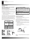
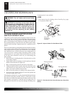
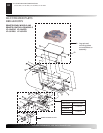
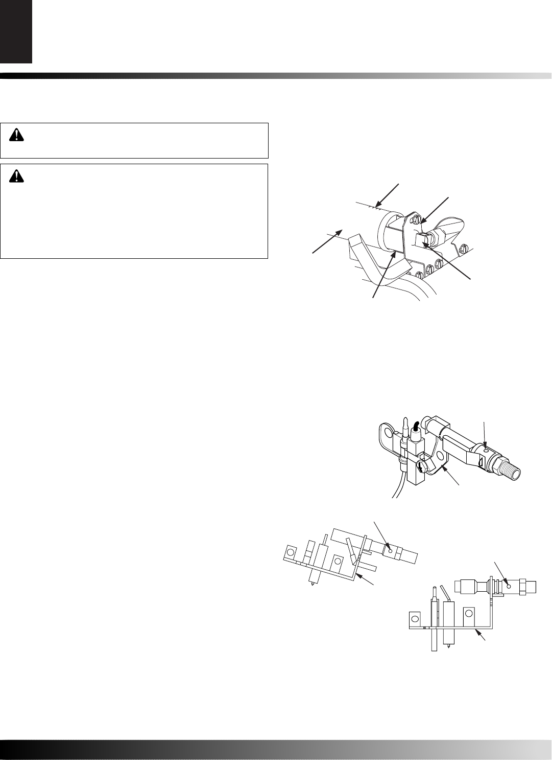
2. Inspect burner, pilot, and primary air inlet opening on injector
holder for dust and dirt (see Figure 26).
3. Blow air through the ports/slots and holes in the burner.
4. Check the injector holder located at the end of the burn er tube
again. Remove any large particles of dust, dirt, lint, or pet hair
with a soft cloth or vacuum clean er nozzle.
5. Blow air into the primary air opening on the injector hold er.
6. In case any large clumps of dust have now been pushed into
the burner re peat steps 3 and 4.
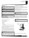
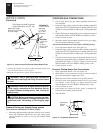
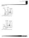
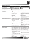
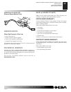
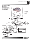
Clean the pilot assembly also. A yellow tip on the pilot fl ame indicates
dust and dirt in the pilot assembly. There is a small pilot air inlet
hole about two inches from where the pilot fl ame comes out of the
pilot assembly (see Figure 27). With the unit off, lightly blow air
through the air inlet hole. You may blow through a drinking straw
CLEANING AND MAINTENANCE
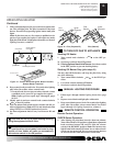
Figure 26 - Injector Holder On Out let Burn er Tube
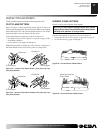
Pilot Assembly
Pilot Air
Inlet Hole
CLEANING AND MAINTENANCE
Cleaning Burner Injector Holder and Pilot Air Inlet Hole
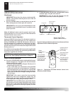
Figure 27 - Pilot Inlet Air Hole (Your pilot may vary from pilots
shown)
Pilot Assembly
Pilot Air Inlet Hole
Pilot Assembly
Pilot Air Inlet Hole
if com pressed air is not available.
LOGS
• If you remove logs for cleaning, re fer to Installing Logs, page
14, to prop er ly re place logs.
Burner
Tube
Injector
Holder
Injector
Primary Air
Inlet Opening
(at bottom)
Ports
Slots