


21
104636
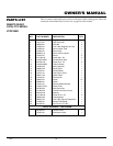
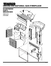
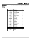
OWNER’S MANUAL
CLEANING AND
MAINTENANCE
WARNING: Turn off heater
and let cool before cleaning.
CAUTION: You must keep
control areas, burner, and circu-
lating air passageways of heater
clean. Inspect these areas of
heater before each use. Have
heater inspected yearly by a quali-
fied service person. Heater may
need more frequent cleaning due
to excessive lint from carpeting,
pet hair, bedding material, etc.
LOGS
• If you remove logs for cleaning, refer to
Installing Logs, page 13, to properly re-
place logs.
• Replace log(s) if broken or chipped
(dime-sized or larger).
CLEANING BURNER
INJECTOR HOLDER AND
PILOT AIR INLET HOLE
The primary air inlet holes allow the proper
amount of air to mix with the gas. This pro-
vides a clean burning flame. Keep these holes
clear of dust, dirt, and lint. Clean these air inlet
holes prior to each heating season. Blocked
air holes will create soot. We recommend that
you clean the unit every three months during
operation and have heater inspected yearly by
a qualified service person.
We also recommend that you keep the burner
tube and pilot assembly clean and free of dust
and dirt. To clean these parts we recommend
using compressed air no greater than 30 PSI.
Your local computer store, hardware store, or
home center may carry compressed air in a
can. You can use a vacuum cleaner in the
blow position. If using compressed air in a
can, please follow the directions on the can.
If you don't follow directions on the can, you
could damage the pilot assembly.
1. Shut off the unit, including the pilot.
Allow the unit to cool for at least thirty
minutes.
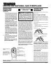
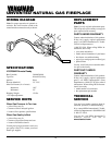
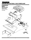
2. Inspect burner, pilot, and primary air
inlet holes on injector holder for dust
and dirt (see Figure 33).
3. Blow air through the ports/slots and
holes in the burner.
4. Check the injector holder located at the
end of the burner tube again. Remove any
large particles of dust, dirt, lint, or pet hair
with a soft cloth or vacuum cleaner nozzle.
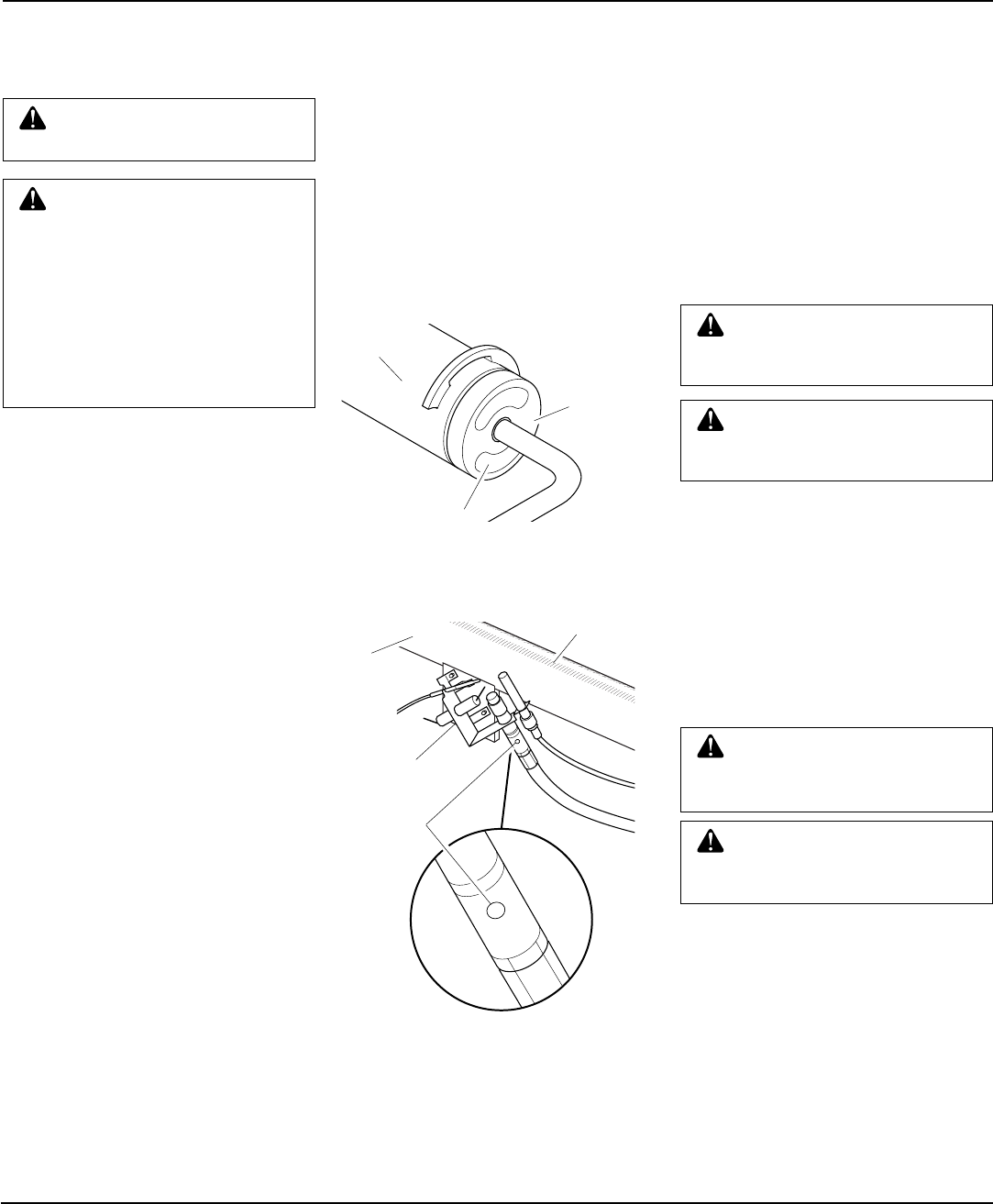
Figure 33 - Injector Holder On Outlet
Burner Tube
5. Blow air into the primary air holes on
the injector holder.
6. In case any large clumps of dust have
now been pushed into the burner repeat
steps 3 and 4.
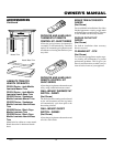
Clean the pilot assembly also. A yellow tip on
the pilot flame indicates dust and dirt in the pilot
assembly. There is a small pilot air inlet hole
about two inches from where the pilot flame
comes out of the pilot assembly (see Figure 34).
With the unit off, lightly blow air through the air
inlet hole. You may blow through a drinking
straw if compressed air is not available.
Burner
Tube
Injector Holder
(May Be Brass
or Aluminum
Depending on
Model)
Primary Air Inlet
Holes (Shape of
Holes May Vary
by Model)
Figure 34 - Pilot Inlet Air Hole
Burner
Tube
Pilot
Assembly
Pilot Air
Inlet
Hole
Ports/Slots
MAIN BURNER
Periodically inspect all burner flame holes
with the heater running. All slotted burner
flame holes should be open with yellow
flame present. All round burner flame holes
should be open with a small blue flame
present. Some burner flame holes may be-
come blocked by debris or rust, with no flame
present. If so, turn off heater and let cool.
Either remove blockage or replace burner.
Blocked burner flame holes will create soot.
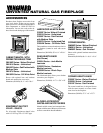
FRONT WINDOW GLASS
WARNING: You must operate
this fireplace with the front win-
dow assembly in place.
WARNING: Never clean the
glass when it is hot. Handle glass
with care.
You will have to clean the glass periodically.
During start up, condensation will form on the
inside of the glass which causes lint, dust, and
other airborne particles to cling to the glass
surface. Also initial paint curing may deposit
a slight film on the glass. Clean the glass with
a clean soft cloth and a nonabrasive household
cleaner to avoid scratching the glass. Clean the
glass only when necessary.
CATALYTIC FILTER
CAUTION: Do not operate
heater with a broken, damaged,
or missing catalytic component.
WARNING: Do not submerge
the filter in any water solutions. Do
not use any liquid to clean filter.
The catalytic filter requires cleaning at least
once a year to work effectively. After remov-
ing front window assembly (see step 1, page
11), remove the six (6) hex nuts holding the
catalytic filter. Lower the filter down and out
of firebox. Handle the filter with care. Do not
bend or destroy the steel spiral coils con-
tained within the catalyst. Use a brush with
soft bristles, a vacuum with a brush attach-
ment, or compressed air to remove loose dirt,
debris, and dust. After cleaning, install the
catalytic filter back to the unit.