


10
104636
UNVENTED NATURAL GAS FIREPLACE
®
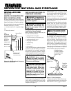
13"
16"
19"
21"
2
1
/2"
6"
8"
10"
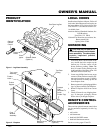
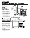
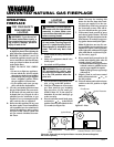
Minimum Non-
Combustible
Material
Supplied Firebox
Hood Must Be
Used at All Times
INSTALLING GAS PIPING TO
FIREPLACE LOCATION
Installation Items Needed
Before installing fireplace, make sure you
have the items listed below.
• piping (check local codes)
• sealant (resistant to LP/propane gas)
• equipment shutoff valve *
• test gauge connection *
• sediment trap
• tee joint
• pipe wrench
* An CSA/AGA design-certified equipment
shutoff valve with 1/8" NPT tap is an accept-
able alternative to test gauge connection.
Purchase the optional CSA/AGA design-
certified equipment shutoff valve from your
dealer. See Accessories, pages 22 and 23.
WARNING: A qualified ser-
vice person must connect fire-
place to gas supply. Follow all
local codes.
WARNING: Never connect
fireplace to private (non-utility)
gas wells. This gas is commonly
known as wellhead gas.
CAUTION: Use only new,
black iron or steel pipe. Inter-
nally-tinned copper tubing may
be used in certain areas. Check
your local codes. Use pipe of 1/2"
diameter or greater to allow
proper gas volume to fireplace. If
pipe is too small, undue loss of
pressure will occur.
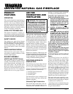
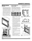
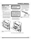
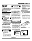
MANTEL CLEARANCES FOR
BUILT-IN INSTALLATION
If placing mantel above built-in fireplace,
you must meet minimum clearance between
mantel shelf and top of fireplace opening.
If your installation does not meet the below
minimum clearances, you must:
• raise the mantel to an acceptable height,
OR
• remove the mantel.
Figure 16 - Minimum Mantel Clearances
for Built-In Installation
Mantel Shelf
Note:
All Vertical
measurements
are from top of
fireplace
opening to
bottom of
mantel shelf.
INSTALLATIONS
Continued
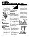
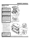
WARNING: This appliance re-
quires a 1/2" NPT (National Pipe
Thread) inlet connection to the
pressure regulator.
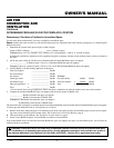
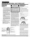
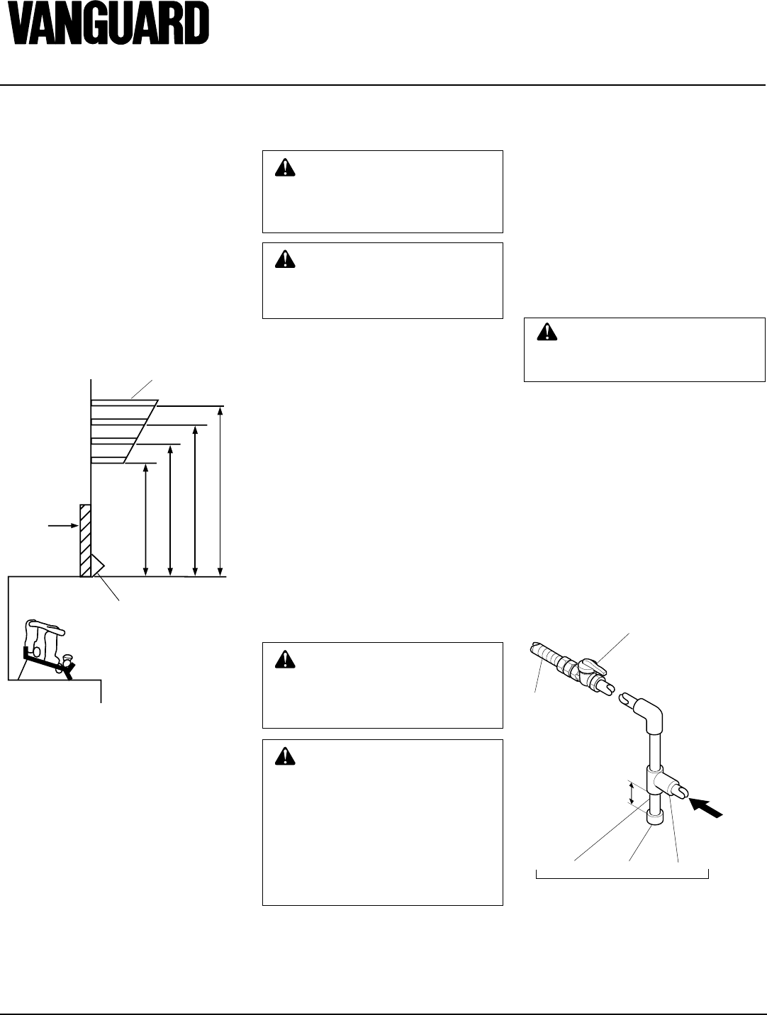
CSA/AGA Design-
Certified Equipment
Shutoff Valve With
1/8" NPT Tap*
3" Minimum
From Gas
Meter
(5" W.C. to
10.5" W.C.
Pressure)
Approved
Flexible Gas
Line
Pipe Nipple Cap Tee Joint
Sediment Trap
Figure 17 - Gas Connection
* Purchase the optional CSA/AGA design-
certified equipment shutoff valve from your
dealer. See Accessories, pages 22 and 23
CAUTION: Use pipe joint seal-
ant that is resistant to liquid pe-
troleum (LP) gas.
We recommend that you install sediment
trap in supply line as shown in Figure 17.
Locate sediment trap where it is within
reach for cleaning. Install in piping system
between fuel supply and fireplace. Locate
sediment trap where trapped matter is not
likely to freeze. A sediment trap traps mois-
ture and contaminants. This keeps them
from going into fireplace gas controls. If
sediment trap is not installed or is installed
wrong, fireplace may not run properly.
Installation must include an equipment
shutoff valve, and a plugged 1/8" NPT tap.
Locate NPT tap within reach for test gauge
hook up. NPT tap must be upstream from
fireplace (see Figure 17).
IMPORTANT:
Install equipment shutoff
valve in an accessible location. The equip-
ment shutoff valve is for turning on or
shutting off the gas to the appliance.
Check your building codes for any special
requirements for locating equipment shutoff
valve to fireplaces.
Apply pipe joint sealant lightly to male pipe
threads. This will prevent excess sealant
from going into pipe. Excess sealant in pipe
could result in clogged fireplace valves.
Never use thread sealant on flare threads.