


112126-01B
For more information, visit www.desatech.com
For more information, visit www.desatech.com
14
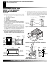
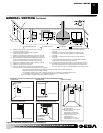
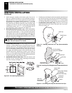
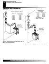
3. Attach vent pipe assembly to the burner system. Set stove in
front of it’s permanent location to insure minimum clearances.
Mark the wall for a 10"(25.4cm) square hole (for noncombus-
tible material such as masonry block or concrete, a 7
1
/2" (19.1cm)
diameter hole is acceptable). See Figure 24. The center of the
hole should line up with the center-line of the horizontal rigid
vent pipe. Cut a 10"x10" (25.4cm x 25.4cm) square hole through
combustible exterior wall (7
1
/2" [19.1cm] diameter hole if
noncombustible). Frame as necessary (see Figure 24).
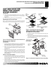
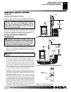
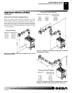
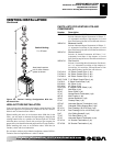
4. Noncombustible Exterior Wall: Apply a bead of non-harden-
ing mastic around the outside edge of the vent cap. Position the
vent cap in the center of the 7
1
/2" (19.1cm) hole on the exterior
wall with the arrow on the vent cap pointing up. Attach the vent
cap with four wood screws provided (see Figure 25).
Note
: Re-
place the wood screws with appropriate fasteners for stucco, brick,
concrete, or other types of siding.
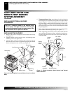
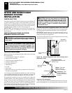
Combustible Exterior Wall: For vinyl siding, stucco, or wood
exteriors, a siding standoff must be installed between the vent
cap and exterior wall. The siding standoff prevents excessive
heat from damaging siding materials. Siding materials must be
cut to accommodate standoff. Bolt the vent cap to the stand-
off. Apply non-hardening mastic around outside edge of the
standoff. Position the standoff/cap assembly in the center of
the 10" (25.4cm) square hole and attach to exterior wall with
wood screws provided (see Figure 26). The siding standoff must
sit flush against the exterior fascia material.
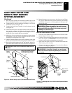
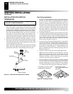
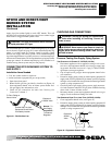
5. Combustible Exterior Wall Only: Slide the interior wall
firestop over the vent pipe before connecting the horizontal
run to the vent cap (see Figure 27).
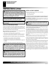
WARNING: Do not recess vent termination in to
any wall. This will cause a fire hazard.
6. Carefully move the fireplace with vent assembly attached toward
the wall and insert the vent pipe into the horizontal termination.
The pipe overlap should be a minimum of 1
1
/4" (3.2cm). Fasten
all vent pipe connections (except vent cap) with screws provided.
7. Combustible Exterior Wall Only: Slide the wall firestop
against the interior wall surface and attach with screws pro-
vided (see Figure 27).
VENTING INSTALLATION
Continued
VENTING INSTALLATION
Installation for Horizontal Termination (Cont.)
Figure 25 - Installing Horizontal Vent Cap (Noncombustible
Exterior)
Figure 26 - Installing Vinyl Siding Standoff (Combustible Exterior
Wall)
Figure 27 - Connecting Vent Cap with Horizontal Vent Pipe
Figure 24 - Vent Opening Requirements
Wood Screw
Vent Cap
Cut Vinyl Siding
Away to Fit Standoff
Wood Screw
Bolt
Standoff
Vent Cap
Apply Mastic
to All Four Sides
Vent Cap
(Horizontal
Termination)
Interior Wall
Surface
Interior Wall Firestop
(Combustible
Exterior Wall Only)
Horizontal
Vent Pipe
Screw