


11
105683
OWNER’S MANUAL
For more information, visit www.desatech.com
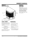
INSTALLATION
Continued
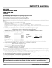
OPERATING HEATER
FOR YOUR SAFETY
READ BEFORE
LIGHTING
WARNING: If you do not fol-
low these instructions exactly, a
fire or explosion may result caus-
ing property damage, personal
injury or loss of life.
A. This appliance has a pilot which must
be lighted by hand. When lighting the
pilot, follow these instructions exactly.
B. BEFORE LIGHTING smell all
around the appliance area for gas. Be
sure to smell next to the floor because
some gas is heavier than air and will
settle on the floor.
WHAT TO DO IF YOU SMELL GAS
• Do not try to light any appliance.
• Do not touch any electric switch; do
not use any phone in your building.
• Immediately call your gas supplier
from a neighbor’s phone. Follow
the gas supplier’s instructions.
• If you cannot reach your gas sup-
plier, call the fire department.
C. Use only your hand to push in or turn
the gas control knob. Never use tools.
If the knob will not push in or turn
by hand, don’t try to repair it, call a
qualified service technician or gas
supplier. Force or attempted repair
may result in a fire or explosion.
D. Do not use this appliance if any part
has been under water. Immediately call
a qualified service technician to inspect
the appliance and to replace any part
of the control system and any gas con-
trol which has been under water.
Continued
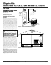
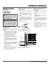
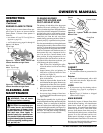
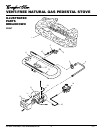
13. Install plastic control knob onto output
shaft of speed control housing (see Fig-
ure 15). Place speed control housing
just inside control compartment door
in front of stove (see Figure 16).
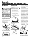
14. Using two screws provided in blower
kit, mount blower speed control hous-
ing to mounting tab in left side of lower
control compartment (see Figure 16).
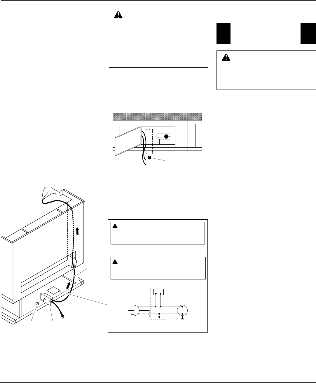
15. Check to make sure that the power cord is
completely clear of blower wheel and there
are no foreign objects in blower wheel.
16. Carefully replace stove top panel. Align
holes and replace six screws removed
in step 1.
17. Peel off the backing paper and stick
the supplied wiring diagram decal on
the stove floor bottom as shown in
Figure 15.
18. Plug power cord into a convenient 3-prong
grounded wall receptacle near the stove.
Figure 16 - Installing Blower Control Housing
Blower Speed
Control Housing
Power
Cord
Speed Control
Housing
Control
Knob
Figure 15 - Routing Power Cord
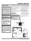
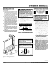
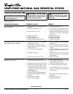
101584-05
120 Vac. 60 Hz. . 78 Amps
DESA International, Bowling Green, KY
Variable
Fan Switch
WhiteWhite
Black
Green
On
110/115
V.A.C.
Blower
Motor
Black
Black
Black
Off
WARNING: Never attempt to service heater while it
is plugged in, operating, or hot. Burns and electrical
shock could result. Only a qualified service person
should service or repair heater.
If any of the original wire as supplied with the appliance must be
replaced, it must be replaced with 105°C wire or it’s equivalent.
WARNING: Label all wires prior to disconnection
when servicing controls. Wiring errors can cause im-
proper and dangerous operation. Verify proper opera-
tion after servicing.
Wiring
Diagram
Decal
19. Using speed control knob, turn blower
on and check for operation.
20. All remaining parts from blower kit
may be discarded.
WARNING: ELECTRICAL
GROUNDING INSTRUCTIONS
This appliance is equipped with a
three-prong (grounding) plug for
your protection against shock
hazard and should be plugged
directly into a properly grounded
three-prong receptacle.