


10
104412
VENT-FREE PROPANE/LP GAS HEATER
BLUE-FLAME
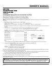
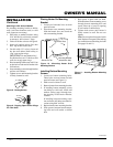
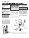
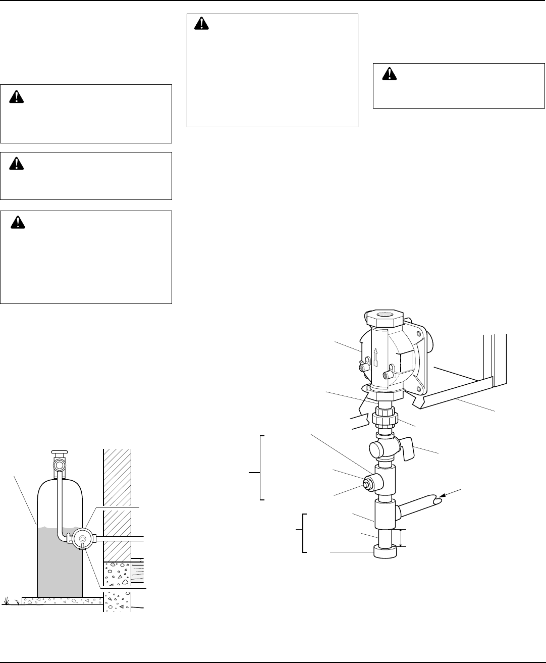
Figure 13 - Gas Connection
* A CSA/AGA design-certified equipment shutoff valve with 1/8" NPT tap is an acceptable
alternative to test gauge connection. Purchase the optional CSA/AGA design-certified
equipment shutoff valve from your dealer. See Accessories, page 22.
Install sediment trap in supply line as shown
in Figure 13. Locate sediment trap where it
is within reach for cleaning. Locate sedi-
ment trap where trapped matter is not likely
to freeze. A sediment trap traps moisture
and contaminants. This keeps them from
going into heater controls. If sediment trap
is not installed or is installed wrong, heater
may not run properly.
IMPORTANT:
Hold pressure regulator
with wrench when connecting it to gas pip-
ing and/or fittings.
CAUTION: Use pipe joint seal-
ant that is resistant to liquid pe-
troleum (LP) gas.
Installation must include a equipment shutoff
valve, union, and plugged 1/8" NPT tap.
Locate NPT tap within reach for test gauge
hook up. NPT tap must be upstream from
heater (see Figure 13).
IMPORTANT:
Install an equipment shutoff
valve in an accessible location. The equip-
ment shutoff valve is for turning on or
shutting off the gas to the appliance.
Typical Inlet Pipe Diameters
20,000 Btu/Hr models 3/8" or greater
30,000 Btu/Hr models 1/2" or greater
CONNECTING TO GAS
SUPPLY
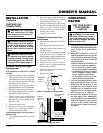
The installer must supply an external regu-
lator. The external regulator will reduce
incoming gas pressure. You must reduce
incoming gas pressure to between 11 and 14
inches of water. If you do not reduce incom-
ing gas pressure, heater regulator damage
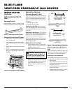
could occur. Install external regulator with
the vent pointing down as shown in Figure
12. Pointing the vent down protects it from
freezing rain or sleet.
WARNING: A qualified service
person must connect heater to
gas supply. Follow all local codes.
CAUTION: Never connect
heater directly to the propane/LP
supply. This heater requires an
external regulator (not supplied).
Install the external regulator be-
tween the heater and propane/LP
supply.
Figure 12 - External Regulator with Vent
Pointing Down
CAUTION: Use only new,
black iron or steel pipe. Inter-
nally-tinned copper tubing may
be used in certain areas. Check
your local codes. Use pipe of 1/2"
diameter or greater to allow
proper gas volume to heater. If
pipe is too small, undue loss of
pressure will occur.
INSTALLATION
Continued
External
Regulator
Propane/LP
Supply
Tank
Vent
Pointing
Down
3" Minimum
Tee Joint
Reducer Bushing
to 1/8" NPT
1/8" NPT Plug Tap
Test
Gauge
Connection *
Tee Joint
Pipe Nipple
Cap
Heater
Cabinet
Pressure
Regulator
3/8" NPT
Pipe
Nipple
Ground Joint
Union
Equipment
Shutoff
Valve *
Typical Inlet
Pipe From
External Regulator
(11" W.C. to 14"
W.C. Pressure)
Sediment
Trap
Note:
Burner bracket
not shown for clarity
Apply pipe joint sealant lightly to male
threads. This will prevent excess sealant
from going into pipe. Excess sealant in pipe
could result in clogged heater valves.
WARNING: This appliance re-
quires a 3/8" NPT (National Pipe
Thread) inlet connection to the
pressure regulator.