


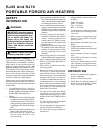
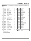
10
104950
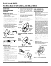
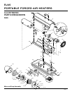
PORTABLE FORCED AIR HEATERS
RJ45 And RJ70
NOZZLE (RJ45)
1. Remove upper shell (see Upper Shell
Removal, page 8).
2. Remove fan (see Fan, page 8).
3. Remove fuel and air line hoses from
nozzle adapter.
4. Turn nozzle adapter 1/4 turn to left and
pull toward motor to remove.
5. Place nozzle adapter into vise and
lightly tighten.
6. Carefully unscrew nozzle from the
nozzle adapter using 5/8" socket wrench.
7. Blow compressed air through face of
nozzle. This will free any dirt in
nozzle area.
8. Inspect nozzle seal for damage.
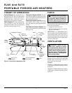
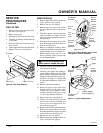
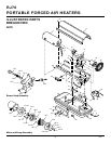
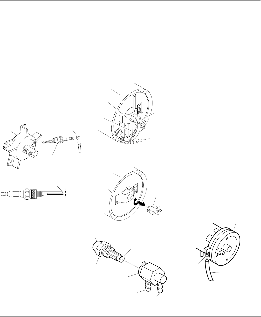
Figure 14 - Removing Air and Fuel Line
Hoses
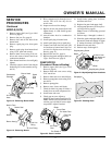
SERVICE
PROCEDURES
Continued
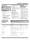
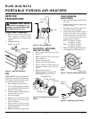
Figure 12 - Spark Plug Removal
Figure 13 - Spark Plug Gap
Spark Plug Wire
Burner
Head
Spark Plug
Gap
2.2 mm
Bend Here to Adjust Gap
SPARK PLUG (RJ70)
1. Remove upper shell (see Upper Shell
Removal, page 8).
2. Remove fan (see Fan, page 8).
3. Remove spark plug wire from spark plug.
4. Remove spark plug from burner head
using 13/16" open-end wrench.
5. Clean and regap spark plug electrodes
to 2.2 mm.
6. Install spark plug in burner head.
7. Attach spark plug wire to spark plug.
8. Replace fan (see Fan, page 8).
9. Replace fan guard and upper shell (see
Upper Shell Removal, page 8).
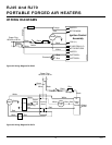
Fuel Line
Hose
Nozzle
Adapter
Combustion
Chamber
Air Line
Hose
9. Screw nozzle into nozzle adapter until
nozzle seats. Tighten 7200-8000 grams/
centimeter using 5/8" socket wrench.
10. Install nozzle adapter into nozzle
adapter bracket.
11. Connect and route fuel line hose and
air line hose to nozzle assembly. See
Fuel and Air Line Replacement and
Proper Routing, page 10.
12. Replace fan (see Fan, page 8).
13. Replace fan guard and upper shell (see
Upper Shell Removal, page 8).
Figure 15 - Removing Nozzle Assembly
Nozzle
Adaptor
Bracket
Nozzle
Adapter
Combustion
Chamber
Figure 16 - Nozzle and Nozzle Adapter
Nozzle Face
Nozzle
Nozzle Adapter
Air Line
Fitting
Fuel Line
Fitting
Nozzle Seal
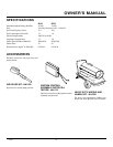
FUEL AND AIR LINE
REPLACEMENT AND
PROPER ROUTING
1. Remove upper shell (see Upper Shell
Removal, page 8).
2. Remove side cover screws using 5/16"
nut driver (see Figure 9, page 9).
3. Remove side cover.
4. Inspect fuel and air line hoses for cracks
and/or holes. If fuel line hose is dam-
aged, disconnect from nozzle adapter or
burner head (see Figure 14 or Figure 18,
page 11) and from fuel filter (see Fuel
Filter, page 9). If air line hose is dam-
aged, disconnect from nozzle adapter or
burner head (see Figure 14 or Figure 18,
page 11) and from barb fitting on pump
end cover (see Figure 17).
5. Install new air and/or fuel line. Attach
one end of air line hose to barb fitting
on pump end cover (see Figure 17) and
the other end to nozzle adapter or
burner head (see Figure 14 or Figure
18, page 11). Attach one end of fuel line
hose to fuel filter (see Fuel Filter, page
9) and the other end to nozzle adapter
(see Figure 14 or Figure 18, page 11).
Route air and fuel line approximately
as shown in Figure 14 (RJ45) or 18
(RJ70), page 11.
Note:
Hoses are not to touch photocell
bracket.
6. Replace side cover.
7. Replace upper shell and fan guard (see
Upper Shell Removal, page 8).
Figure 17 - Air Hose to Barb Fitting
Pump End Cover
Barb
Fitting
Air Hose
Ignitor and
Photocell
wires
through
this hole