


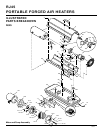
9
104950
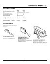
OWNER’S MANUAL
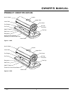
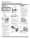
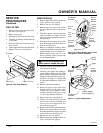
Fuel Filter
Side Cover
Upper Fuel Line
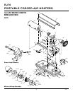
Figure 9 - Fuel Filter Removal
FUEL FILTER
1. Remove side cover screws using 5/16"
nut-driver (see Figure 9).
2. Remove side cover.
3. Pull upper fuel line off fuel filter neck.
4. Carefully pry bushing and fuel filter out
of fuel tank.
5. Wash fuel filter with clean fuel and re-
place in tank.
6. Attach upper fuel line to fuel filter neck.
7. Replace side cover (see Figure 9).
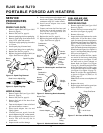
SERVICE
PROCEDURES
Continued
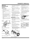
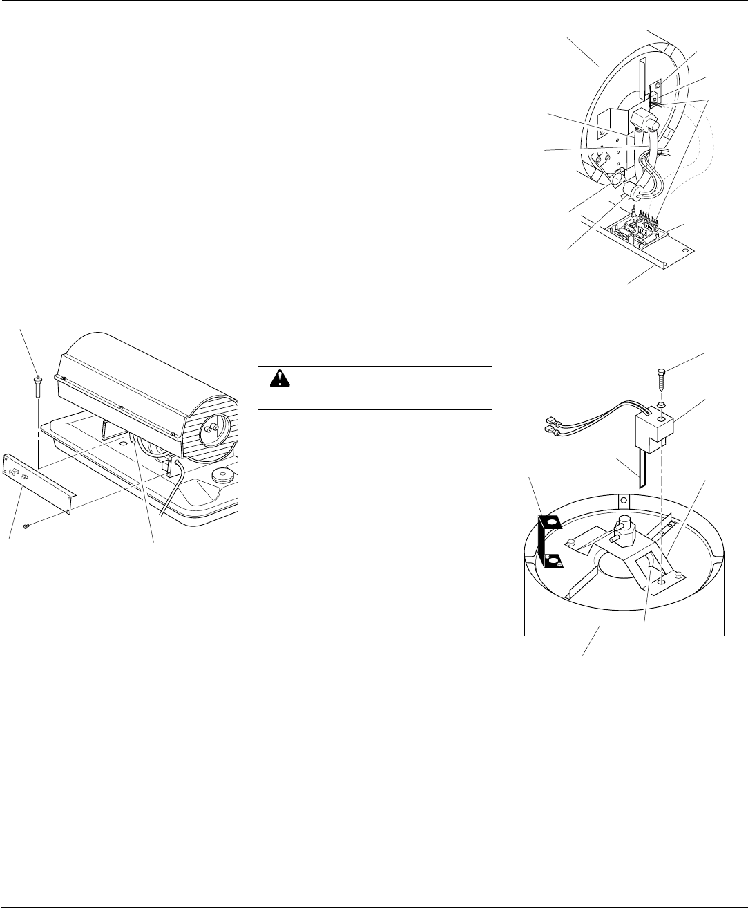
IGNITOR (RJ45)
1. Remove upper shell and fan guard (see
Upper Shell Removal, page 8).
2. Remove fan (see Fan, page 8).
3. Remove side cover screws with a 5/16"
nut driver. Remove side cover (see Fig-
ure 9).
4. Disconnect ignitor wires from ignition
control assembly (see Figure 10). Pull
the ignitor wires up through the hole in
the lower shell.
5. Disconnect fuel line hose and air line
hose. Remove photocell from photocell
bracket (see Figure 10).
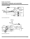
6. Remove combustion chamber. Stand
combustion chamber on end with nozzle
adapter bracket on top (see Figure 11).
7. Remove ignitor screw with a 1/4" nut
driver. Carefully remove ignitor from
nozzle adapter bracket.
CAUTION: Do not bend or strike
ignitor element. Handle with care.
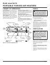
Figure 10 - Disconnecting Ignitor Wires
from Ignition Control Assembly
8. Carefully remove replacement ignitor
from styrofoam packing.
9. Carefully guide ignitor into opening in
nozzle adapter bracket. Do not strike
ignitor element. Attach ignitor to nozzle
adapter bracket with screw using a 1/4"
nut driver (see Figure 11). Torque 1800
to 3500 grams/centimeters. Do not over
torque.
10. Replace combustion chamber.
11. Route the ignitor wires back down
through the hole in the lower shell.
Connect wires to the ignition control
assembly. See Wiring Diagrams, page
12, for correct terminal locations.
12. Replace side cover (see Figure 9).
13. Connect and route fuel line hose and
air line hose to nozzle assembly. See
Fuel and Air Line Replacement and
Proper Routing, page 10.
14. Replace photocell in photocell bracket.
Route wires between hoses and back
down through the hole in the lower shell
with ignitor wires (see Figure 10).
15. Replace fan (see Fan, page 8).
16. Replace fan guard and upper shell (see
Upper Shell Removal, page 8).
Combustion
Chamber
Ignitor
Wires
(Gray)
Ignitor
Nozzle
Adapter
Bracket
Ignition
Control
Assembly
Side Cover
Photocell
Bracket
Photocell
Assembly
Air Line
Hose
Fuel
Line
Hose
Figure 11 - Ignitor Replacement
Combustion
Chamber
Photocell
Bracket
Ignitor
Ignitor
Screw
Nozzle
Adapter
Bracket
Nozzle Adapter
Bracket Opening
Ignitor
Element
Continued