


901265-01E
For more information, visit www.desatech.com
For more information, visit www.desatech.com
5
5
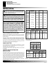
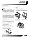
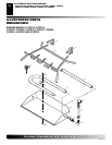
INSTALLING DAMPER CLAMP
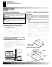
Secure the damper stop clamp provided to the leading edge of the
damper as shown in Figure 3. If for any reason this clamp doesn't
work on your fireplace, another suitable clamp or permanent stop
must be installed, or the damper blade must be cut or removed.
Damper Clamp
Damper
Clamp
Damper
Manufactured
Fireplace
Masonry Fireplace
Figure 3 - Attaching Damper Clamp
INSTALLATION
Continued
Damper
Damper
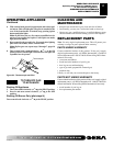
CONNECTING TO GAS SUPPLY
WARNING: A qualified service person must con-
nect log set to gas supply. Follow all local codes.
Installation Items Needed
Before installing log set, make sure you have the items listed below.
• piping (check local codes)
• sealant (resistant to Propane/LP gas)
• equipment shutoff valve
• test gauge connection
• adjustable (crescent) wrench or pliers
• sediment trap
• tee joint
• pipe wrench
CAUTION: Use only new, black iron or steel pipe.
Internally-tinned copper tubing may be used in certain
areas. Check your local codes. Use pipe of 1/2" diam-
eter or greater to allow proper gas volume to log set. If
pipe is too small, undue loss of pressure will occur.
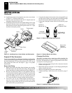
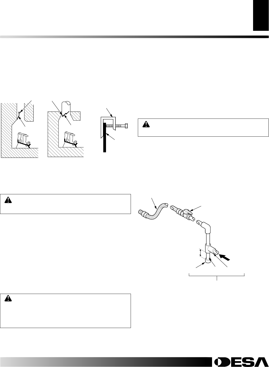
We recommend that you install a sediment trap in supply line as
shown in Figure 4. Locate sediment trap where it is within reach for
cleaning. Install in piping system between fuel supply and heater.
Locate sediment trap where trapped matter is not likely to freeze. A
sediment trap traps moisture and contaminants. This keeps them
from going into log set controls. If sediment trap is not installed or
is installed wrong, log set may not run properly.
Installation must include a equipment shutoff valve, union, and
plugged 1/8" NPT tap. Locate NPT tap within reach for test gauge
hook up. NPT tap must be upstream from log set (see Figure 4).
IMPORTANT:
Install equipment shutoff valve in an accessible
location. The equipment shutoff valve is for turning on or shutting
off the gas to the appliance.
Apply pipe joint sealant lightly to male NPT threads. This will
prevent excess sealant from going into pipe. Excess sealant in pipe
could result in a clogged burner injector.
WARNING: Use pipe joint sealant that is resistant
to liquid petroleum (LP) gas.
Figure 4 - Gas Connection
* Purchase the optional CSA design-certified equipment shutoff
valve from your dealer. See Accessories, page 15.
** Minimum inlet pressure for purpose of input adjustment.
3" Minimum
Sediment Trap
From Gas Meter
(5" W.C.** to 10.5"
W.C. Pressure)
CSA Design-Certified
Equipment Shutoff
Valve With 1/8" NPT
Tap*
Approved Flexible Gas Hose
(if allowed by local codes)
Tee Joint
Pipe Nipple
Cap
INSTALLATION
Installing Damper Clamp
Connecting to Gas Supply