


901265-01E
For more information, visit www.desatech.com
For more information, visit www.desatech.com
4
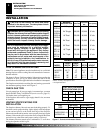
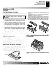
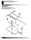
MINIMUM FIREBOX SIZES
FRONT BACK
MODEL WIDTH* WIDTH** DEPTH HEIGHT
18DR/SR 28" 16" 14" 18"
24DR/SR 29
3
/4" 17" 15
1
/2" 18"
30DR 36" 27" 18" 18"
BFL18 28" 16" 15
1
/2" 18"
BFL24 30" 22" 15
1
/2" 18"
INSTALLATION
WARNING: Before installing in a solid fuel burning
fireplace, the chimney flue and firebox must be cleaned
of soot, creosote, ashes and loose paint by a qualified
chimney cleaner. Creosote will ignite if highly heated.
A dirty chimney flue may create and distribute soot
within the house. Inspect chimney flue for damage.
NOTICE: Installation, service, and repair of this appli-
ance must be performed by a qualified installer,
service agency, company or gas supplier experi-
enced with this type of gas appliance. Only factory
authorized components listed in these instructions
may be used in accordance with the manufacturer’s
instructions and all codes and requirements of the
authority having jurisdiction. Any modifications to
this kit, or use of unauthorized components or acces-
sory items will void the manufacturer’s warranty, and
may result in a hazardous condition.
CHECK GAS TYPE
Use only natural gas. If your gas supply is not natural gas, you must
install ON/OFF Safety Valve/Pilot Kit (see Accessories, page 15).
Call dealer where you bought log set.
If the fireplace does not have a gas supply shutoff valve, one must
be installed.
CAUTION: Do not remove the metal data plates
attached to the burner pan. The data plates contain
important warranty information.
FLUE OPENING SPECIFICATIONS
Note:
This vented appliance must be installed only in a solid-fuel
burning fireplace with a working flue and constructed of noncom-
bustible material.
The charts in Figure 2 indicate technical information regarding the
installation of your gas log set. Please make sure that all of the
specifications shown are applicable before installation is attempted.
The fireplace must include a working flue and venting system with
the minimum openings shown in the Figure 2.
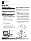
VENTING SPECIFICATIONS FOR
INSTALLATION
The fireplace chimney flue and vent must be drafting properly. To
check the vent for proper drafting: Light a tightly rolled newspaper
on one end and place it at the inside front edge of the fireplace.
Observe the smoke and be sure the vent is properly drawing it up the
chimney. If the smoke spills out into the room, extinguish the flame
and remove any obstruction until proper venting is achieved.
The chimney flue must remain open a minimum of 3" at all times
during the operation of this log set.
BURNER
MODEL DESCRIPTION
VVSR18 18" Single 50,000 40,000 8" dia.
FVSR18
VVSR24 24" Single 60,000 50,000 8" dia.
FVSR24
VVDR18 18" Dual 55,000 45,000 8" dia.
FVDR18
VVDR24 24" Dual 65,000 55,000 8" dia.
FVDR24
VVDR30 30" Dual 70,000 60,000 8" dia.
FVDR30
CBFL18 18" Triple 65,000 55,000 8" dia.
BFLT18
CBFL24 24" Triple 70,000 60,000 8" dia.
BFLT24
Btu Input
Natural Gas
Btu Input
Propane/LP
Gas
Minimum
Vent Opening
*Add 6" if safety valve/pilot is used
**At depth indicated
FUEL INLET PRESSURE
SPECIFICATIONS (W.C.)
Min. Max.
NG 5.5" 10.5"
LP 11" 13"
Figure 2 - Technical Information Charts
BURNER ORIFICE
LOG NATURAL PROPANE/LP
SIZE IN. NUM. IN. NUM.
18SR/DR .120 31 .073 49
24SR/DR/BFL18 .129 30 .086 44
30DR/BFL24 .1405 28 .089 43
INSTALLATION
Flue Opening Specifications
Check Gas Type
Venting Specifications for Installation