


104163-01H
4
For more information, visit www.desatech.com
For more information, visit www.desatech.com
INSTALLATION
WARNING: Review and understand the warnings
in the
Safety Information
section, page 2. They are
needed to safely operate this heater. Follow all local
codes when using this heater.
1. Provide propane supply system (see Propane Supply).
2. Connect POL fitting on hose/regulator assembly to propane
tank(s). Turn POL fitting counterclockwise into threads on tank.
Tighten firmly using wrench.
IMPORTANT:
Position regula-
tor so that hose leaving the regulator is in a horizontal position
(see Figure 6, page 5). This places the regulator vent in the
proper position to protect it from the weather.
WARNING: Test all gas piping and connections
for leaks after installation or servicing. Never use an
open flame to check for a leak. Apply a mixture of
liquid soap and water to all joints. Bubbles forming
show a leak. Correct all leaks at once.
PROPANE SUPPLY
Propane gas and propane tank(s) are to be furnished by the user.
Use this heater only with a propane vapor withdrawal supply system.
See Chapter 5 of the Standard for Storage and Handling of Liquefied
Petroleum Gas, ANSI/NFPA 58 and/or CAN/CGA B149.2. Your local
library or fire department will have this booklet.
The amount of propane gas ready for use from propane tanks varies.
Two factors decide this amount:
1. The amount of propane gas in tank(s)
2. The temperature of tank(s)
This heater is designed to operate with a minimum 20-pound
propane tank. You may need two or more tanks or one larger tank
in colder weather. Use a 100-pound tank for longer operation or in
very cold weather. Less gas is vaporized at lower temperatures.
Your local propane gas dealer will help you select the proper supply
system. The minimum surrounding air temperature rating for each
heater is -20°F (-29°C).
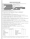
Average Temp (°F) No. Of Tanks
At Tank Location (100-pound)
40° 1
32° 1
20° 1
10° 1
0° 1
-10° 2
-20° 2
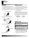
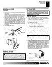
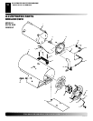
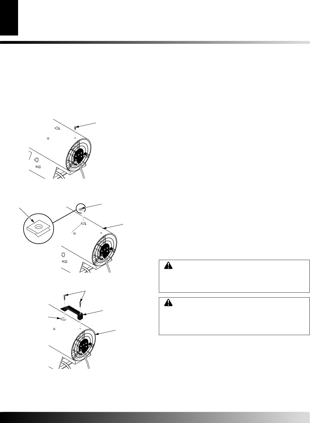
ASSEMBLY
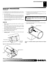
1. Remove screw from top of fan guard. Discard screw.
2. Insert nut clip (provided with handle) with flat side facing up
through slot in top of shell. Align holes in nut clip with screw
hole behind slot in top of shell. (see Figure 4).
3. Place handle over hole and clip. Insert two screws (provided
with handle) through handle and tighten into shell. Make sure
rear screw goes through shell and into fan guard. Tighten
screws firmly.
Figure 3 - Removing Screw from Top of Fan Guard
Figure 4 - Installing Nut Clip
Figure 5 - Attaching Handle
Remove
Screw
Nut Clip
Slot
Shell
Screws
Handle
Rear of
Heater
Nut Clip
Flat Side Facing Up
ASSEMBLY
PROPANE SUPPLY
INSTALLATION