


6
103910
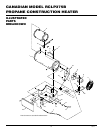
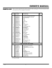
PROPANE CONSTRUCTION HEATER
CANADIAN MODEL RCLP375B
LP-PFA/P 024
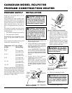
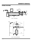
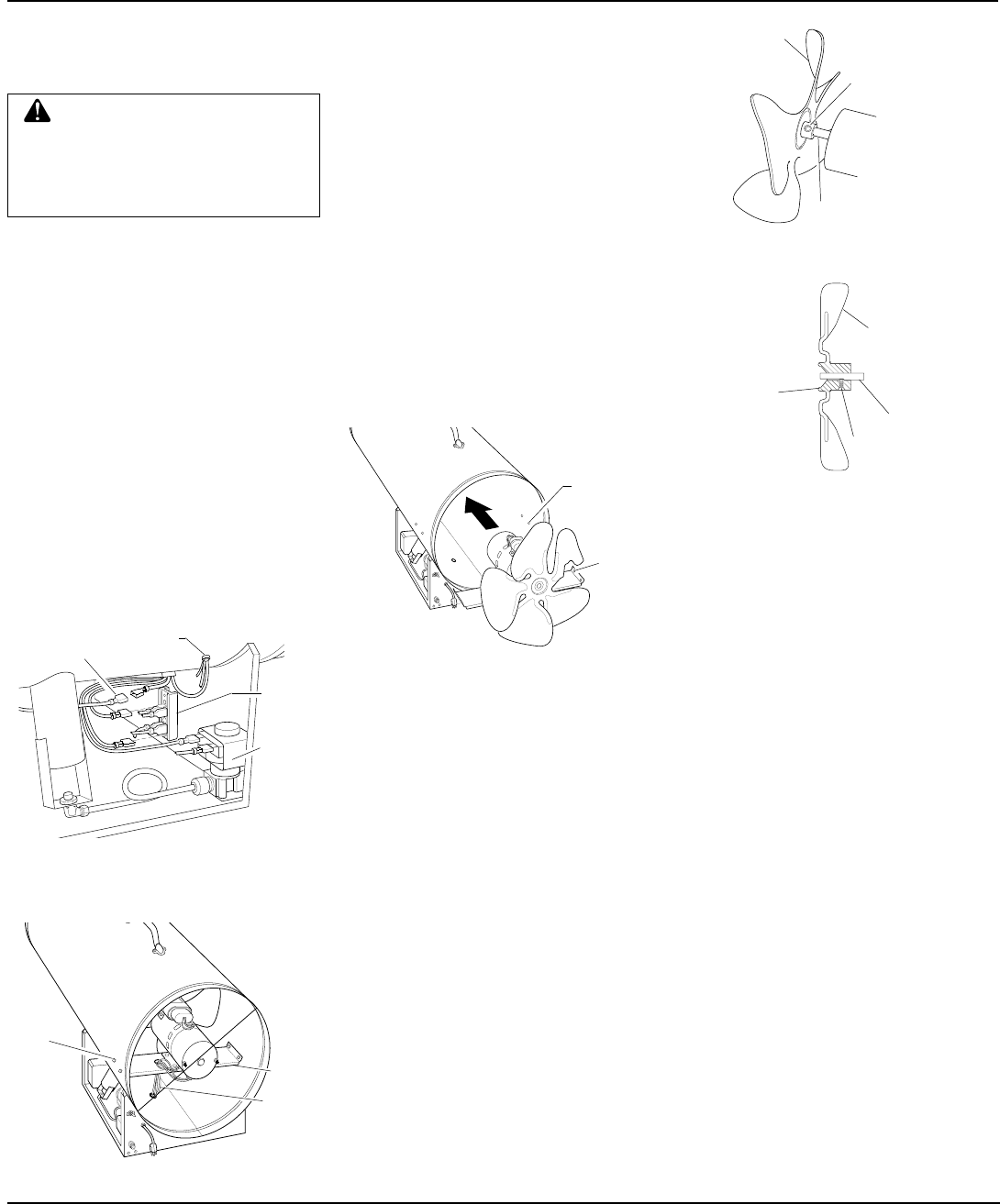
Figure 9 - Fan, Motor Shaft, and Setscrew
Location
Figure 8 - Fan and Motor Turned Around
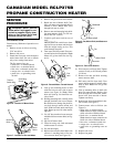
SERVICE
PROCEDURE
CLEANING FAN
Clean fan every 500 hours of operation or as
needed.
1. Remove screws on side cover using
5/16" nut-driver.
2. Remove side cover.
3. Detach the five motor wires from parts
under heater shell. Be sure to detach
only wires coming from motor.
The five motor wires are:
• white wire—to terminal board
• black wire—to terminal board
• blue wire—to thermal switch wire
• orange wire—to solenoid valve
• green wire—to grounding screw
on shell
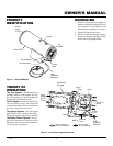
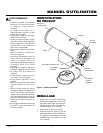
Figure 7 - Location of Fan and Motor
WARNING: Never service
heater while it is plugged in, con-
nected to propane supply, oper-
ating, or hot. Severe burns and
electrical shock can occur.
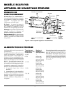
Figure 6 -
Location of Motor Wires
Terminal
Board
Grounding
Screw
Thermal
Switch Wire
Solenoid
Valve
Motor
Wires
Mounting
Bolts
Motor
Mount
4. Remove fan guard from rear of heater.
5. Reach into rear of heater shell. Care-
fully pull motor wires through hole in
bottom of shell.
Note:
Pull wires
through hole one at a time.
6. Remove nuts and mounting bolts hold-
ing motor mount to shell. Use 3/8" nut-
driver and 7/16" wrench.
7. Carefully pull motor and fan out of
shell.
IMPORTANT:
Be careful not to dam-
age fan. Do not set motor and fan down
with the weight resting on fan. This
could damage fan pitch.
8. Turn motor and fan around. Place mo-
tor and fan into shell backwards.
Note:
Motor will go into shell first (see Fig-
ure 8).
LP-PFA/P 026
Rear
Mounting
Hole
First
Hole
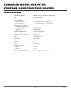
FAN CROSS SECTION LP-PFA/P 013
Motor Shaft
Setscrew
Hub
Fan
Figure 10 - Fan Cross Section
9. Line up rear mounting holes in shell
with first hole on each side of motor
mount (see Figure 8).
Note:
When
holes are lined up, fan should be out-
side of shell.
10. Holding mounting bolt, carefully reach
through fan blades into rear of heater.
Be careful not to damage fan pitch. In-
sert bolt through motor mount and
shell. With free hand, attach nut finger
tight. Repeat process for other mount-
ing hole.
11. Use 1/8" hex wrench to loosen setscrew
which holds fan to motor shaft (see Fig-
ure 9).
12. Slip fan off motor shaft.
13. Clean fan using soft cloth moistened
with kerosene or solvent.
14. Dry fan thoroughly.
15. Replace fan on motor shaft. Make sure
setscrew is touching back of flat sur-
face on motor shaft (see Figure 10).
16. Place setscrew on flat of shaft. Tighten
setscrew firmly to 40-50 inch-pounds
(5.6 N•m).
17. Remove two nuts and bolts securing
motor mount to shell.
18. Pull motor and fan from shell. Turn
motor and fan around. Carefully place
back in shell.
Note:
Fan will go into
shell first.
19. Line up mounting holes in shell with
holes on motor mount. Replace four
bolts through shell and motor mount.
Insert bolts from outside of heater.
Tighten nuts firmly.
20. Route motor wires through hole in bot-
tom of shell (see Figure 7).
21. Connect motor wires as follows (see
Figure 6):
• white wire—to terminal board.
Note:
Attach to empty connector on
white wire side of terminal board.
• black wire—to terminal board.
Note:
Attach to empty connector on
black wire side of terminal board.
• blue wire—to thermal switch wire
• orange wire—to solenoid valve
• green wire—to grounding screw on
shell
22. Replace side cover.
23. Replace fan guard.
FAN LP-PFA/P 023A
Fan
Setscrew
Motor shaft