


12
102438
50 ROTOR
PFA/P 056
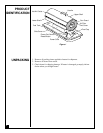
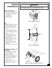
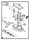
Pump Rotor
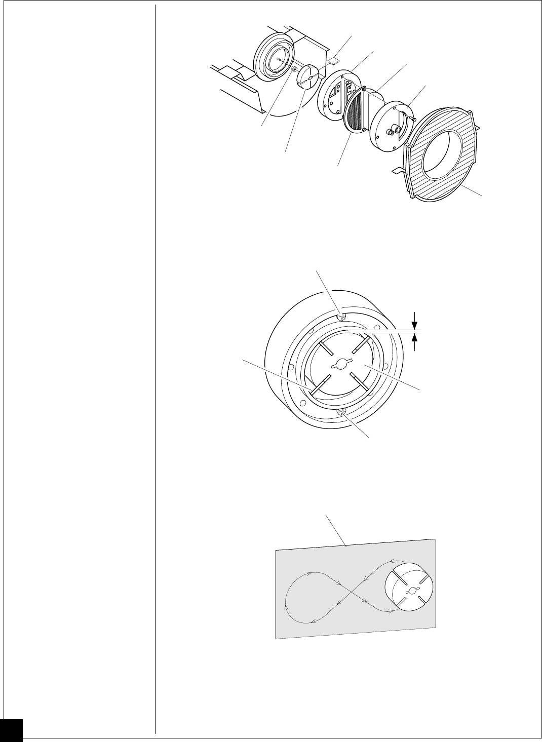
(Procedure if rotor is binding)
1. Remove upper shell (see page
9).
2. Remove filter end cover
screws using 5/16" nut-
driver.
3. Remove filter end cover and
air filters.
4. Remove pump plate screws
using 5/16" nut-driver.
5. Remove pump plate.
6. Remove rotor, insert, and
blades.
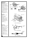
7. Check for debris in pump. If
debris is found, blow out with
compressed air.
8. Install insert and rotor.
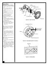
9. Check gap on rotor. Adjust to
.003"/.004" if needed (see
Figure 15).
Note:
Rotate rotor one full turn
to insure the gap is .003"/.004"
at tightest position. Adjust if
needed.
10.Install blades, pump plate, air
filters, and filter end cover.
11.Replace fan guard and upper
shell.
12.Adjust pump pressure (see
page 10).
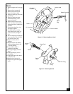
Note:
If rotor is still binding, pro-
ceed as follows.
13.Perform steps 1 through 6 (see
above).
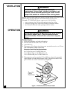
14.Place fine grade sandpaper
(600 grit) on flat surface. Sand
rotor lightly in “figure 8” mo-
tion four times (see Figure 16).
15.Reinstall insert and rotor.
16.Perform steps 10 through 12
above.
Figure 16 - Sanding Rotor
Sandpaper
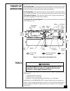
Figure 15 - Gap Adjusting Screw Locations
Gap Adjusting Screw
Blade
Gap Adjusting Screw
.003"/.004" Gap
Measured With
Feeler Gauge
Rotor
Blade
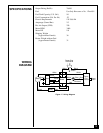
Pump Plate
Filter End Cover
Air Intake Filter
Fan Guard
Air Output Filter
Insert
Rotor
Figure 14 - Rotor Location