


www.desatech.com
13118621-01B
INSTALLATION
Continued
IMPORTANT: Install an equipment shutoff
valve in an accessible location. The equip-
ment shutoff valve is for turning on or shutting
off the gas to the appliance.
Apply pipe joint sealant lightly to male NPT
threads. This will prevent excess sealant from
going into pipe. Excess sealant in pipe could
result in clogged heater valves.
WARNING: Use pipe joint
sealant that is resistant to liquid
petroleum (LP) gas.
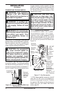
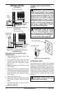
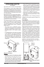
Install sediment trap in supply line as shown
in Figure 17, page 12. Locate sediment trap
where it is within reach for cleaning. Locate
sediment trap where trapped matter is not
likely to freeze. A sediment trap traps mois-
ture and contaminants. This keeps them from
going into heater controls. If sediment trap is
not installed or is installed wrong, heater may
not run properly.
IMPORTANT: Hold the pressure regulator
with wrench when connecting it to gas pip-
ing and/or ttings. Do not over tighten pipe
connection to regulator. The regulator body
could be damaged.
CHECKING GAS CONNECTIONS
WARNING: Test all gas piping
and connections, internal and
external to unit, for leaks after
installing or servicing. Correct
all leaks at once.
WARNING: Never use an
open ame to check for a leak.
Apply a noncorrosive leak detec-
tion uid to all joints. Bubbles
forming show a leak. Correct all
leaks at once.
CAUTION: For propane/LP
gas, make sure external regula-
tor has been installed between
propane/LP supply and heater.
See guidelines under Connect-
ing to Gas Supply, page 12.
PRESSURE TESTING GAS SUPPLY
PIPING SYSTEM
Test Pressures In Excess Of 1/2 PSIG
(3.5 kPa)
1. Disconnect appliance with its appliance
main gas valve (control valve) and equip-
ment shutoff valve from gas supply piping
system. Pressures in excess of 1/2 psig
will damage heater regulator.
2. Cap off open end of gas pipe where equip-
ment shutoff valve was connected.
3. Pressurize supply piping system by either
opening propane/LP supply tank valve
for propane/LP gas or opening main gas
valve located on or near gas meter for
natural gas or using compressed air.
4. Check all joints of gas supply piping sys-
tem. Apply a noncorrosive leak detection
uid to all joints. Bubbles forming show a
leak.
5. Correct all leaks at once.
6. Reconnect heater and equipment shutoff
valve to gas supply. Check reconnected
ttings for leaks.
Test Pressures Equal To or Less Than
1/2 PSIG (3.5 kPa)
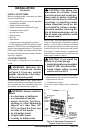
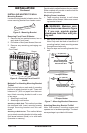
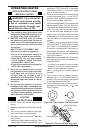
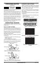
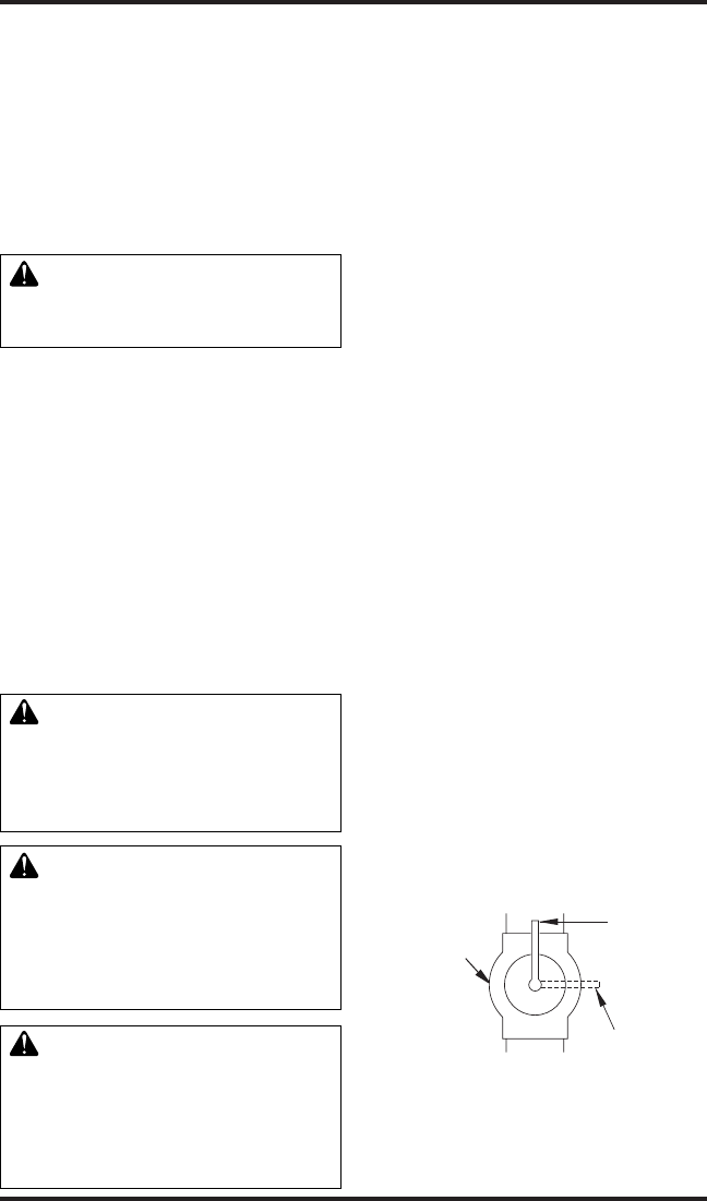
1. Close equipment shutoff valve (see
Figure 18).
2. Pressurize supply piping system by either
opening propane/LP supply tank valve
for propane/LP gas or opening main gas
valve located on or near gas meter for
natural gas or using compressed air.
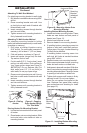
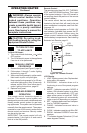
3. Check all joints from gas meter for natural
gas (see Figure 19) or propane/LP supply
tank for propane/LP gas, to equipment
shutoff valve (see Figure 20). Apply a
noncorrosive leak detection uid to all
joints. Bubbles forming show a leak.
4. Correct all leaks at once.
Figure 18 - Equipment Shutoff Valve
Open
Closed
Equipment
Shutoff Valve