


www.desatech.com
111347-01E 15
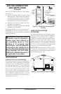
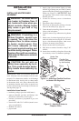
PRESSURE TESTING HEATER GAS
CONNECTIONS
1. Open equipment shutoff valve (see Figure 15,
page 14).
2. Open main gas valve located on or near gas
meter for natural gas or open propane/LP
supply tank valve.
3. Make sure control knob of heater is in the OFF
position.
4. Check all joints from equipment shutoff valve
to control valve (see Figures 16 and 17). Apply
noncorrosive leak detection fluid to all joints.
Bubbles forming show a leak.
5. Correct all leaks at once.
6. Light heater (see Operating Heater, page 16)
depending on your model). Check all other
internal joints for leaks.
7. Turn off heater (see To Turn Off Gas to Ap
-
pliance, page 18 or 20, depending on your
model).
INSTALLATION
Continued
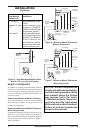
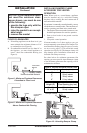
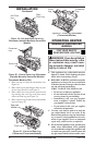
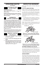
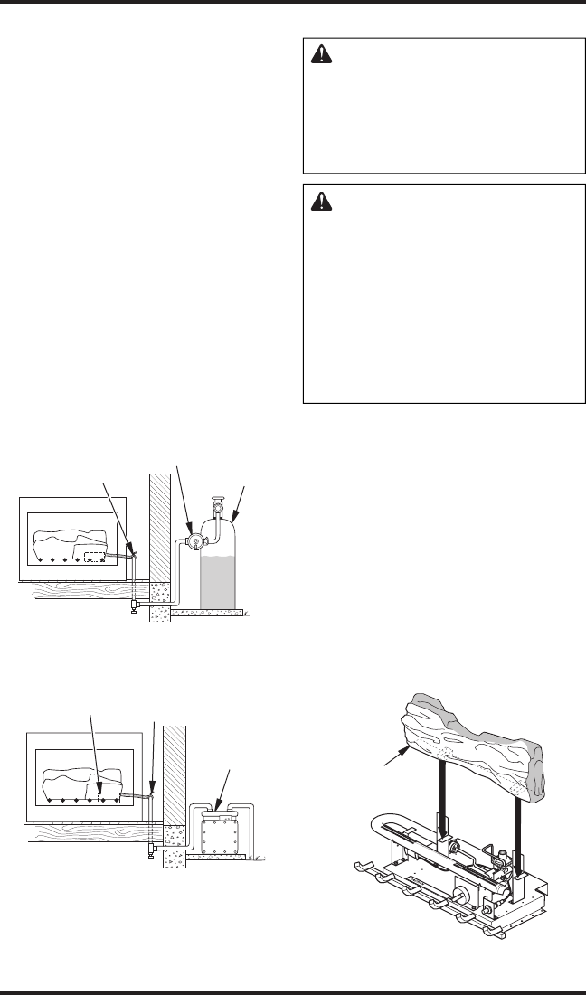
Figure 16 - Checking Gas Joints
(Propane/LP only)
Gas Control
Valve Location
Propane/LP
Supply Tank
Equipment
Shutoff Valve
Figure 17 - Checking Gas Joints (Natural
Gas Only)
Gas Meter
Gas Control
Valve Location
Equipment
Shutoff Valve
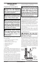
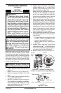
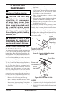
Figure 18 - Rear Log Placement (Variable
Manually-Controlled Models)
Rear Log
INSTALLING LOGS
WARNING: Failure to position
the parts in accordance with these
diagrams or failure to use only
parts specifically approved with
this heater may result in property
damage or personal injury.
CAUTION: After installation
and periodically thereafter,
check to ensure that no flame
comes in contact with any log.
With the heater set to HI, check
to see if flames contact any log. If
so, reposition logs according to
the log installation instructions
in this manual. Flames contact-
ing logs will create soot.
It is very important to install the logs exactly as
instructed. Do not modify logs. Only use logs
supplied with heater.
Variable Manually-Controlled Models
(LSL)
1. Place rear log onto rear brackets making sure
brackets fit into recess on bottom of log (see
Figure 18).
2. Place left front log on grate fingers as shown
in Figure 19, page 16. Place right front log on
grate fingers and on left front log (see Figure
19, page 16).
3. Slide control cover log into position between
two front logs assuring the cover log seats into
cutout section (see Figure 20, page 16).