


105501-01F
For more information, visit www.desatech.com
For more information, visit www.desatech.com
19
19
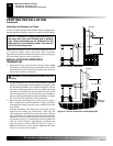
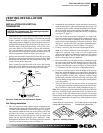
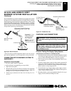
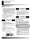
We recommend that you install a sediment trap in supply line as shown
in Figure 39. Locate sediment trap where it is within reach for cleaning.
Install in piping system between fuel supply and burner system. Locate
sediment trap where trapped matter is not likely to freeze. A sediment
trap traps moisture and contaminants. This keeps them from going into
burner system gas controls. If sediment trap is not installed or is installed
wrong, burner system may not run properly.
STOVE AND DIRECT-VENT BURNER SYSTEM INSTALLATION
Installing Gas Piping To Stove/Burner System Location (Cont.)
Connecting Stove/Burner System To Gas Supply
Checking Gas Connections
STOVE AND DIRECT-VENT
BURNER SYSTEM INSTALLATION
Continued
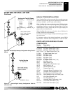
* The CSA design-certified equipment shutoff valve may be sup-
plied with the appliance or you can purchase it from your dealer.
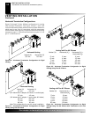
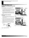
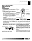
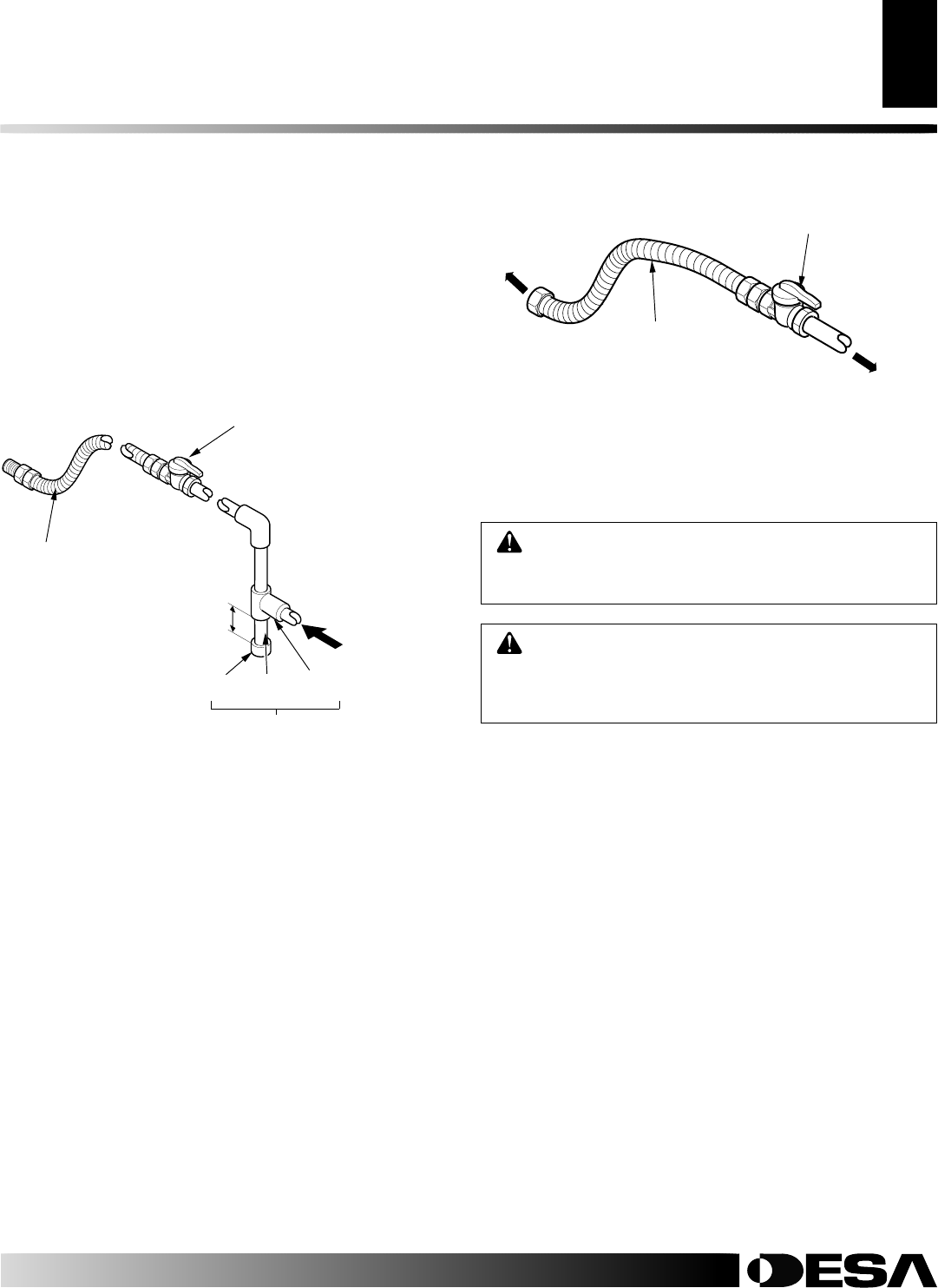
Figure 40 - Flexible Gas Line
CONNECTING STOVE/BURNER SYSTEM TO
GAS SUPPLY
Installation Items Needed
• 5/16" hex socket wrench or nut-driver
• sealant (resistant to propane/LP gas, not provided)
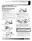
1. Open lower door panel.
2. Route flexible gas line (provided by installer) from equipment
shutoff valve to burner system. Route flexible gas supply line
through slot in stove bottom and attach to valve.
3. Check all gas connections for leaks. See Checking Gas Con-
nections.
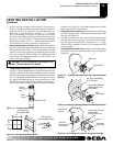
CHECKING GAS CONNECTIONS
WARNING: Test all gas piping and connections
for leaks after installing or servicing. Correct all leaks
at once.
WARNING: Never use an open flame to check for
a leak. Apply a noncorrosive leak detection solution
to all gas joints. Bubbles forming show a leak. Cor-
rect all leaks at once.
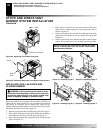
Pressure Testing Gas Supply Piping System
Test Pressures In Excess Of 1/2 PSIG (3.5 kPa)
1. Disconnect burner system and its individual equipment shutoff
valve from gas supply piping system. Pressures in excess of 1/2
psig (3.5 kPa) will damage burner system gas regulator.
2. Cap off open end of gas pipe where equipment shutoff valve
was connected.
3. Pressurize supply piping system by either opening propane/LP
supply tank valve for propane/LP gas burner system or open-
ing main gas valve located on or near gas meter for natural gas
burner system, or using compressed air.
4. Check all joints of gas supply piping system. Apply a noncor-
rosive leak test solution to all gas joints. Bubbles forming show
a leak. Correct all leaks at once.
5. Reconnect burner system and equipment shutoff valve to gas
supply. Check reconnected fittings for leaks.
Figure 39 - Gas Connection
CSA Design-Certified Equipment
Shutoff Valve with 1/8" NPT Tap*
3" Minimum
Propane/LP - From
External Regulator
(11" W.C. to 14"
W.C. Pressure)
Natural - From Gas
Meter (5" W.C. to
10.5" W.C. Pressure)
Approved Flexible
Gas Line
Cap Pipe Tee
Nipple Joint
Sediment Trap
To Flare Fitting on
Control Valve
Flexible Gas Line from
Equipment Shutoff Valve
Provided by Installer
Equipment Shutoff Valve
Natural - To Gas Supply
Propane/LP - To
External Regulator