


10
CAST IRON STOVE AND BURNER SYSTEM
107600
For more information, visit www.desatech.com
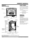
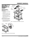
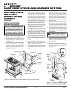
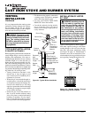
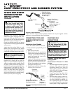
Figure 23 - Typical B-Vent Installation
WARNING: Installation should
only be made by qualified per-
sons who are familiar with the
safety procedures required for
the installation of the product,
who are equipped with the proper
tools and testing instruments,
and who have achieved proper
certification of licensing. Instal-
lations made by unqualified per-
sons can result in the risk of in-
jury or electrical shock which can
be serious or even fatal.
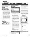
INSTALLATION OF LISTED
B-1 VENT
Figure 24 and Figures 25 and 26, page 11,
show other options for the gas vent. When
venting through a side wall your vent pipe
must have the proper temperature rating
(see Figure 26, page 11). Manufacturer’s
clearances must also be maintained. Con-
sult the authority having jurisdiction in your
area regarding venting through side wall.
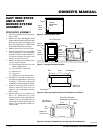
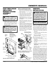
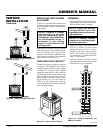
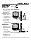
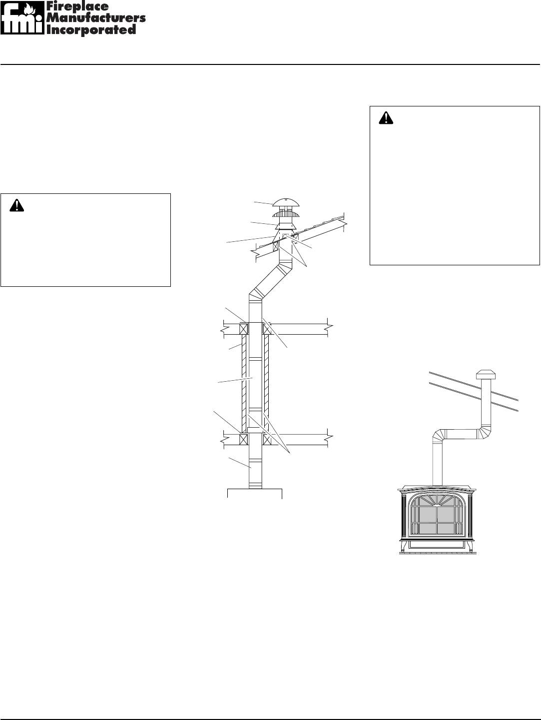
Figure 24 - Vertical Venting Through
Ceiling Using Two 90
°
Elbows
Round Top
Storm Collar
Flashing
Roof
Support
25mm (1")
Clearance to
Combustible
Material
Firestop
Spacer
Keep Electrical
Wires and Building
Insulation Away
from Gas Vent and
Out of the Required
Air Space
Enclosure
Wall
Gas Vent
Length
25mm (1")
Clearance to
Combustibles
Support
Plate
Adjustable
Length
• This heater must be properly connected to
a venting system. This heater is equipped
with a vent safety shutoff system.
• Use only vents labeled "FOR EXTE-
RIOR USE" above the roofline.
• Consult the authority having jurisdic-
tion to select the correct gas vent di-
ameter. Avoid using a larger than nec-
essary diameter.
It is very important that the venting system
maintain its balance between the combus-
tion air intake and the flue gas exhaust.
Certain limitations apply to vent configura-
tions and must be strictly followed.
WARNING: This gas stove with
burner system and vent assembly
must be vented directly to the out-
side. The venting system must
NEVER be attached to a chimney
serving a separate solid fuel burn-
ing appliance.
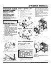
TYPE B-VENT INSTALLATION
(Listed B-0 or Greater)
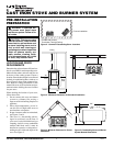
Before beginning installation be sure that the
overall height and gas vent size conform to
building code requirements. Gas vents ex-
tending through pitched roofs can extend a
minimum height of at least 600 mm (2')
higher than any obstruction within 3m (10').
Gas vents extending through flat roofs are
required to extend at least 600 mm (2') above
the roof and at least 600 mm (2') higher than
any portion of the building or adjoining build-
ing within 3m (10') of the gas vent.
• Venting instruction contained in this
manual may or may not apply to your
area. Consult your local authority for re-
quirement in your area.
• Where the gas vent extends through ac-
cessible spaces, it should be enclosed to
avoid personal contact and damage. En-
closure walls should have a fire rating
equal to or greater than the floors through
which the gas vent passes except in single
or two-family dwellings.
• Situate the gas vent in the structure so
that it can be installed without cutting
joists, sills, plates, or major load bearing
partitions or members. It is also impor-
tant to locate the base of the gas vent as
near as possible to the heating appliance.
VENTING
INSTALLATION
Continued